


Hologram 1
The hologram 1 surface can be used to model optically constructed holograms. The hologram surface can be plane, spherical, or conical, and the medium behind the hologram can be air or glass. The glass can also be "MIRROR" which indicates the hologram is constructed and used in reflection. The hologram itself is described by the x, y, and z coordinates of two different construction points, a construction wavelength, and the diffraction order. The hologram deviates ray paths according to the equation

where n ^ is the unit vector normal to the surface of the hologram at ray intersection point, ro is the unit vector along the first construction beam, rr is the unit vector along the second construction beam, r'r is the unit vector along the incident readout beam, r'o is the refracted ray, λc and λp are the construction and playback wavelengths, and m is the diffraction order. A value of m = 0 means the ray is undeviated, while other integral values of m refer to higher diffracted orders. The notation used here is from the book "Aberrations of Optical Systems" by Welford, Adam Hilger (1986). Modeling holograms requires an understanding of their behavior which is beyond the scope of this section, and the user is advised to see the discussion in Welford, or some other reference, before using this feature.
Most holograms are constructed and used in transmission or reflection. There are occasions where the hologram is constructed in transmission, and then the substrate is aluminized and used in reflection. This special case can be simulated with the hologram surface by specifying a negative construction wavelength. Although ray tracing will be correct for this special case, OPD tracing will not work.
By default OpticStudio only models holograms as surface holograms to the extent of deviating ray paths. For other properties such as efficiency, the surface must be set up as a volume hologram using the Volume Hologram? parameter.
The two construction beams are defined in terms of their source points. The x, y, and z coordinates of the source points are measured relative to the hologram vertex coordinate are defined in current lens units. OpticStudio computes the unit vector at the ray-surface intersection point using the local coordinate data and the construction point data for the two construction beams. The construction wavelength always has units of micrometers. If the distance to a source point is greater than 1.0E+08 lens units, the point is assumed to be infinitely distant and the construction beam is a perfect plane wave for that point. This assumption yields more accurate OPD computations than simply entering large coordinate values.
To use a Hologram 1 surface as a volume hologram set the Volume Hologram? parameter to a non-zero value. This allows the input of the volume hologram parameters as listed below.
The hologram is defined by the interference between the two defined construction beams, with no aberrations assumed on the construction beams. Optically fabricated holograms with aberrated construction beams may be modeled in a very general way, see "Optically Fabricated Hologram".
Optically fabricated holograms with aberrated construction beams may be modeled using the "Optically Fabricated Hologram" surface.
The hologram 1 surface assumes that both construction beams diverge from the specified construction points. Because of the reciprocity of the construction beams, this is identical to the case where both construction beams converge toward the construction points. Some hologram fabrication methods require one beam to be converging while the other beam is diverging. See "The hologram 2 surface" for information on this latter type of hologram.
Comment on considering indexes of materials at two sides of the hologram surface
The equation we discussed above doesn't consider the index of the materials at two sides of the hologram surface. If one of the rays is from different material, then we should multiply its unit vector by the index where the ray is in. For example, if the hologram is attached on a glass with index of ng and is used in reflection, then we should write incident readout beam and the refracted beam as ngr'r and ngr'o. This is already handled by OpticStudio. However, the construction beams are always assumed to be in the AIR as there is no parameter for defining the index of the material where the construction beams are. In cases where the hologram is optically manufactured in a non-AIR material, the construction wavelength should be effectively changed from λc to λc/ng.
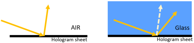
Note that, according to what we discussed above, when the index of the materials at two sides of the hologram are different, we should expect rays to be diffracted to different directions. This is exactly what we would expect for a grating diffraction. Shown below is a sketch that depicts this concept.
PARAMETER DEFINITIONS FOR HOLOGRAM 1 SURFACES (Par 14-21 only available when Par 13 ≠ 0)
| Parameter # | Definition |
| 1 | X coordinate for first construction beam, Construct X1 |
| 2 | Y coordinate for first construction beam, Construct Y1 |
| 3 | Z coordinate for first construction beam, Construct Z1 |
| 4 | X coordinate for second construction beam, Construct X2 |
| 5 | Y coordinate for second construction beam, Construct Y2 |
| 6 | Z coordinate for second construction beam, Construct Z2 |
| 7 | Construction Wavelength, λc |
| 8 | Diffract Order, m |
| 13 | Volume Hologram? (0 for false, 1 for true) |
| 14 | Hologram Thickness (only used for efficiency calculations not ray-tracing) |
| 15 | Refractive index seen by construction beam 1 outside hologram, n1 |
| 16 | Refractive index seen by construction beam 2 outside hologram, n2 |
| 17 | Average refractive index of the hologram emulsion, n |
| 18 | Modulation of the refractive index, dn |
| 19 | Shrinkage (0 for no shrinkage, else scale of thickness e.g. 0.98 is 2% shrinkage) |
| 20 | Index Shift (change of average refractive index after developing) |
| 21 | Consider Fresnel? (0 for false, 1 for true) |
Next: