


Compound Lens
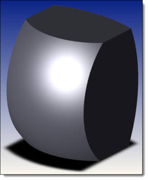
The Compound Lens object is a very general lens object that supports different surfaces and apertures on the front and back faces. Both circular and rectangular apertures are supported. A chip zone and mechanical flat zone can be defined for circular apertures.
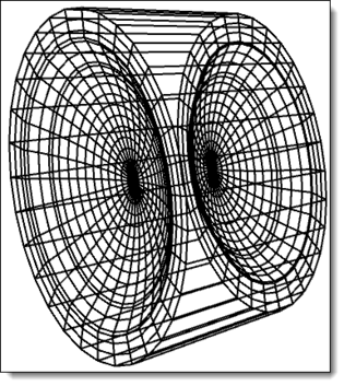
The Compound Lens object is based on two parent surface objects. The parent surface objects include: Standard Surface, Aspheric Surface, Q-type Asphere Surface, Toroidal Surface, Toroidal Odd Asphere, Zernike Surface, Biconic Surface, Biconic Zernike Surface, Extended Polynomial Surface, and Grid Sag Surface.
The Compound Lens object has 7 faces:
0, Side Faces: The side of the lens. If the aperture shape is circular but has different sizes for the front and back surfaces, the edge will be tapered. Note that tapered edges are not supported with rectangular apertures.
1, Front Face: The clear aperture of the front surface.
2, Back Face: The clear aperture of the back surface.
3, Front Chip Zone: The chip zone of the font surface. See "Chip Zone" for more information.
4, Front Flat: The flat mechanical zone of the front surface. See "Mechanical Semi Diameter" for more information. This face is not supported if the aperture shape is rectangular.
5, Back Chip Zone: The chip zone of the back surface.
6, Back Flat: The flat mechanical zone of back surface. This face is not supported if the aperture shape is rectangular.
Comments on the Boundaries (Semi-Diameters) and the validity:
The Compound Lens needs a strict validation on its parameters, namely Semi-Diameters, in order to make sure it is valid.
If a surface is not rotationally-symmetric, it doesn't support mechanical flats on that surface.
If the front or rear surface is not rotationally-symmetric, it doesn't support tapered edges.
The Compound Lens object supports tapered edges when the apertures are circular (Is Rectangular = 0) and when the surfaces on the front and back faces are rotationally symmetric. The Standard Surface and Aspheric Surface types are currently supported.
To try to keep the validation rules as simple as possible, all parameter validation goes from left to right across the editor columns.
For example, the Front Clear will drive validation of the Front Clear + Chip and Front Edge, while the Front Clear + Chip will drive validation for the Front Edge and all Back parameters.
Comments on using a Grid Sag Surface object as one of the parent objects
When one of the parent objects of the Compound Lens is a Grid Sag Surface object, the aperture size of the Compound Lens will be automatically scaled so that it is not larger than the size of that grid file.
Limitations for CAD export
There are some limitations to the Compound Lens object when exporting it as a CAD object. See " CAD Files " for more information about the CAD exchange. The limitations include the following:
- Both the chip zone and the flat mechanical zone are not supported in CAD export. These zones will be combined with the front or back faces.
- To define circular apertures with mechanical flat zones, set the Front/Back Edge Radius to be larger than the Front/Back Chip Radius. The resulting flat zones are modeled with uniformly sampled spline curves. Note that in some extreme cases, the spline curve may not accurately capture the transition from the chip zone to the flat mechanical zone. This will result in some erroneous artifacts in the representation in Shaded Model as well as in any exported CAD files.
Limitations for use with Boolean objects
There are some limitations to the Compound Lens object when using it as a parent object for the Boolean CAD or Boolean Native objects. See " CAD Files " and " Boolean CAD " for more information about these use cases. The limitations include the following:
- If a Compound Lens object is used as one of the parent objects for a Boolean CAD object, there is no way to specify different Coat/Scatter properties for the chip zone and the mechanical flat zone. See " Coat/Scatter " for more information on these properties. Note: This limitation does not apply to the Boolean Native object. The Boolean Native object retains the chip zone and the mechanical flat zone Coat/Scatter properties.
- If a Compound Lens object is used as one of the parent objects for a Boolean CAD object or a Boolean Native object, the Object Viewer will not display the Coat/Scatter properties of the chip zone and the mechanical flat zone. Note: For Boolean Native objects, however, the rays will correctly account for the Coat/Scatter properties of the chip zone and the mechanical flat zone.
The following parameters are used to define the Compound Lens object:
| Parameter # | Description | Face Name | Face # |
| 1-2 | Front/Back Surface #: The parent object number to be used as front and back surfaces. Note that the parent object number must precede the Compound Lens object number in the non-sequential component editor. | All Faces | All Faces |
| 3 | Thickness: The center thickness of the Compound Lens. | Side | 0 |
| 4 | Is Rectangular?: A flag to indicate if the Compound Lens has a circular or rectangular aperture shape. Use 0 for circular, 1 for rectangular. | Side | 0 |
The parameters after #4 are different depending on the Is Rectangular flag (parameter #4).
When the aperture shape is circular (Is Rectangular? = 0), the parameters are:
| Parameter # | Description | Face Name | Face # |
| 5 | Front Clear: The clear semi-diameter aperture of the front face. | Front Face, Front Chip Zone | 1, 3 |
| 6 | Front Chip: The chip zone semi-diameter of the front face. This parameter should be larger or equal than Front Clear Semi-Diameter. | Front Chip Zone, Front Flat | 3, 4 |
| 7 | Front Edge: The mechanical flat semi-diameter of the front face. This parameter should be larger or equal than Front Chip Semi-Diameter. | Front Flat | 4 |
| 8 | Rear Clear: The clear semi-diameter aperture of the back face. | Back Face, Back Chip Zone | 2, 5 |
| 9 | Rear Chip: The chip zone semi-diameter of the back face. This parameter should be larger or equal than Back Clear Semi-Diameter. | Back Chip Zone, Back Flat | 5, 6 |
| 10 | Rear Edge: The mechanical flat semi-diameter of the back face. This parameter should be larger or equal than Back Chip Semi-Diameter. | Back Flat | 6 |
| 11-14 | Unused | NA | NA |
| 15 | Mirror Space?: A flag to indicate whether the lens is defined in mirror space. When Mirror Space? is 1, the lens grows in local -z direction. This is the same as how the lens would be defined after an odd number of mirrors in sequential mode. This flag is used when converting from sequential to non-sequential mode and does not normally need to be used in objects that are manually defined by the user. | NA | NA |
When the aperture shape is rectangular (Is Rectangular? = 1), the parameters are:
| Parameter # | Description | Face Name | Face # |
| 5-6 | X Half Width, Y Half Width: The half width from the lens center to its outmost edge in x and y direction. Tapered edges are not supported for rectangular apertures, so this setting applies to the front and back face. | Front Flat, Back Flat | 3, 5 |
| 7-8 | Front X Clear, Front Y Clear: The chip zone half width from the lens center of the front face. This parameter should be smaller or equal than Half Width X/Y. | Front Face, Front Chip Zone | 1, 3 |
| 9-10 | Unused | ||
| 11-12 | Rear X Clear, Rear Y Clear: The chip zone half width from the lens center of the back face. This parameter should be smaller or equal than Half Width X/Y. | Back Face, Front Chip Zone | 2, 5 |
| 13-14 | Unused | NA | NA |
| 15 | Mirror Space?: A flag to indicate whether the lens is defined in mirror space. When Mirror Space? is 1, the lens grows in local -z direction. This is the same as how the lens would be defined after an odd number of mirrors in sequential mode. | NA | NA |
Next: