


CAD Files

Exports the current lens data to a file as a collection of 3D solids in IGES, SAT, STEP, or STL format.
The STL (Stereo Lithography Language) is particularly useful for sending OpticStudio designs to 3D printing manufacturers.
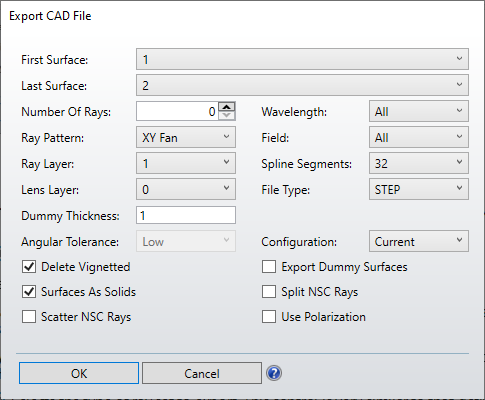
First/Last Surface or Object: The range of surfaces to include in the exported data. In Non-Sequential mode, these options are First and Last Object.
Wavelength: The wavelength number to use for any traced rays to be exported.
Field: The field number to use for any traced rays to be exported.
Number of Rays: The number of rays to trace; the exact meaning depends upon the "Ray Pattern". When exporting to STL format, no rays are exported as STL does not support a line entity.
Split NSC Rays, Scatter NSC Rays, Use Polarization: These settings only affect rays from NSC sources. For more information, see the discussion on the similar controls described in "NSC 3D Layout".
Ray Pattern: Selects the type of ray set to export. This control is very similar to that defined for the 3D layout plot. The solid beam option exports a solid volume representing the envelope of the rays. The solid beam option is only available in sequential mode, and required the marginal rays to be all traceable and unvignetted. The marginal rays may not form a caustic at any surface. Solid beams are not generated for non-sequential surfaces. The number of rays must be at least 8 to export a solid beam, and a smoother solid results if more rays are used.
Lens/Ray Layer: Selects the layers of the output file to place lens and ray data.
Configuration: One or more configurations may be exported at once using this control. Current will export only data from the current configuration. Selecting a configuration number, such as 1, 2, or 3, will export data only from that configuration.
"All By File" will export all configurations, but each to a separate file name. The file name for each configuration is the specified save file name (the save file name is selected after OK is pressed) with the name "_config000x" appended to indicate the data is for configuration "x".
"All By Layer" will export all configurations, but each to a separate layer within the same file. The first configuration will be placed in the layer specified by the lens layer and ray layer settings. Subsequent configurations are placed in the lens and ray layers incremented by 1 for each configuration. For example, if the lens layer is 1 and the ray layer is 10 and there are 3 configurations, then configuration 1 will have lens data in layer 1 and ray data in layer 10. Configuration 2 will have lens and ray data in layers 2 and 11, and configuration 3 will have lens and ray data in layers 3 and 12, respectively.
Note not all CAD software can read the layers information from the exported file. If layers are not supported, use "All By Files" instead of "All By Layers."
"All At Once" will export all configurations at once in a single layer. No attempt is made by OpticStudio to avoid overlapping or redundant data export.
File Type: Selects the output file format type as one of STEP, IGES, SAT and STL formats.
Delete Vignetted: If checked, rays are not included in the data export if they will be vignetted by any surface.
Surfaces As Solids: This control only applies to sequential surfaces, and not NSC surface objects. If checked, surfaces on either side of a glass material will be combined to form a single solid object, where possible. Not all OpticStudio surface types may be combined to form a single solid. Both surfaces must have the same aperture shape to export surfaces as solids. For example, both surfaces must have circular apertures, or both surfaces must have rectangular apertures. If the aperture types do not match then the surfaces are exported as single surfaces.
Note that the first surface may not be the same as the last surface if this option is enabled. If it is, OpticStudio will default to exporting the entire lens system. To export one lens, the first surface should be the front surface and the last surface should be the back surface.
Export Dummy Surfaces: If checked, dummy surfaces will be exported. A dummy surface is a surface that does not reflect or refract rays.
Dummy Thickness: The distance in lens units for the thickness of dummy surfaces if they are automatically converted to solids. Both "Export Dummy Surfaces" and "Surfaces As Solids" need to be checked for this control to have any effect.
Tolerance: The approximate accuracy of the exported objects in lens units. Smaller tolerances yield more accurate representations at the expense of larger exported files and longer computation times.
Angular Tolerance: That setting is available when choosing STL as the File Type. It controls the angular tolerance value used by the CAD libraries which will allow for a more accurate representation of the objects in question in STL. That option has 4 settings: Low, Medium, High, and Presentation. The Low value is the default one.
Spline Segments: The number of segments to use when spline entities are exported.
General Points to Note: The Initial Graphics Exchange Specification (IGES) is an American National Standard whose intended purpose is to facilitate transfer of data between CAD programs. OpticStudio currently supports version 5.3 of the IGES standard.
For more information on IGES, contact U.S. Product Data Association, P. O. Box 3310, Gaithersburg, MD 20885-3310. The STEP format is AP203 as defined by ANS US PRO/IPO-200-203-1994, also available from the U.S. Product Data Association.
OpticStudio exports five types of data:
- Lines: Lines are used to indicate the paths of rays traveling through the optical system. Within GRIN media, rays are exported as a series of line entities. The STL format does not support lines, so rays are not exported.
- Surfaces: Surfaces may be of arbitrary shape, including user defined surfaces and Composite Surfaces; with any aperture shape OpticStudio supports, including user defined apertures. Data for some types of surfaces (particularly aspheres and toroids) which are exported as splines have an accuracy that depends on the number of spline points used; more points yields more accuracy at the expense of larger, slower exported data files. For more information on the limitations of the accuracy of the exported objects see the discussion below.
- Lens Solid: Lens Solids include a non-zero volume enclosed by two surfaces, with the edge region formed by the extrusion of the edges of the two surfaces. Most surfaces surrounding glass with similar shaped apertures (e.g. both surfaces have rectangular apertures) may be exported as solids.
- Faceted Solid: A Faceted Solid is defined by a collection of triangles that form a volume, such as a prism or Fresnel lens. Non-sequential STL and POB objects, among others, are exported as Faceted Solids.
- Parametric Solid: Some NSC objects, such as the Torus Volume, are exported as exact solid NURBS objects.
OpticStudio can export the surface or solid data for all sequential surfaces and non-sequential objects. OpticStudio exports all surfaces and rays in a 3D coordinate system referenced to the global coordinate reference surface.
If exporting surfaces as solids, OpticStudio will export sequential dummy surfaces as thin solids. The front and back face will be of the shape of the surface, with a thickness equal to the dummy thickness in lens units. Mirror surfaces are exported according to the settings for the mirror substrate.
Most NSC objects are exported exactly, or by using one or more spline based surfaces similar to those used for sequential surface export. However, some objects, such as user defined objects, are exported using a faceted approximation to the smooth surfaces. Increasing the drawing resolution for these objects will also increase the resolution of the exported representation.
STL is a faceted format, and all STL surfaces or objects are exported as faceted approximations.
This feature will prompt for the file name and path to save the exported data to. The default file path is the Objects folder, as specified in the Folders section of the OpticStudio Preferences.
Limitations of exported data
OpticStudio supports many types of complex surface and object shapes. Within OpticStudio, these shapes are modeled exactly, yielding the very high numerical precision required for optical ray trace analysis. However, most of the complex optical shapes OpticStudio supports have no analog in commonly used CAD programs, and no exact representation in common CAD file formats such as IGES, STEP, and SAT.
For this reason, OpticStudio must approximate the exact surface shape with the closest available analog within the CAD format. This approximation is usually very good, but for some extremely precise aspheric surface shapes, the approximation is not sufficiently accurate for ray tracing. This is not a limitation of OpticStudio. This is a limitation of the CAD data exchange format and the CAD programs OpticStudio is being asked to export data to. In these rare cases, it may be necessary to recreate the complex geometry within the CAD program directly rather than use the OpticStudio export capability.
For systems with surface apertures, please note that the export of user defined apertures (UDAs) must be verified for the following reasons:
- The accuracy to which the aperture is defined is important to have a successful CAD export. Ensure the aperture boundary shape is correctly formed. For instance, user defined apertures that contain ARC commands where points need to meet up should be particularly checked. OpticStudio cannot tell what the precision requirements are for CAD export as it relates to CAD libraries.
- Some aperture shapes may not be exported. For instance, Spider Obscurations are not currently supported.
There is always the possibility that the conversion from the OpticStudio representation of surfaces and objects to the CAD file format representation will cause a loss of precision.
Next: