


Array Ring
This object is a collection of identical objects, based upon a single parent object, arranged in a ring or arc. The individual array elements are all functionally identical to the parent object, just as if a copy of the parent object had been placed in each array location. The Array Ring object is generally faster to trace and more memory efficient than the equivalent system created by copying the parent object to each element location. The Array Ring object is defined by the following parameters:
| Parameter # | Description | Face Name | Face # |
| 1 | The parent object #. The parent object must precede the array object in the NSC Editor. | NA | NA |
| 2 | The mode number. | NA | NA |
| 3 | The number of array elements, N. | NA | NA |
| 4 | The Radius of the ring or the reference sphere, R, in lens units. | NA | NA |
| 5-9 | The parameters α , β , γ , ẟ , and ε . Whenever these parameters are angles, the units are in degrees. | NA | NA |
The parent object may be any object type, except for a source or detector. If the parent object has the "Object Is A Detector" box checked, this property will be ignored in the array elements. To create an array of sources, see the " Sources " settings in the Object Properties.
The number of array elements may in principle be any number, however, very large arrays may require excessive computation time or computer memory to ray trace or render.
The array elements are arranged on a ring (or arc). There are two ways to define the positions of the array elements, defined by the mode flag. Mode 0 results in a ring of objects in a plane. Mode 1 creates a ring of objects on a reference sphere. The method for placing each array elements is as follows for each mode:
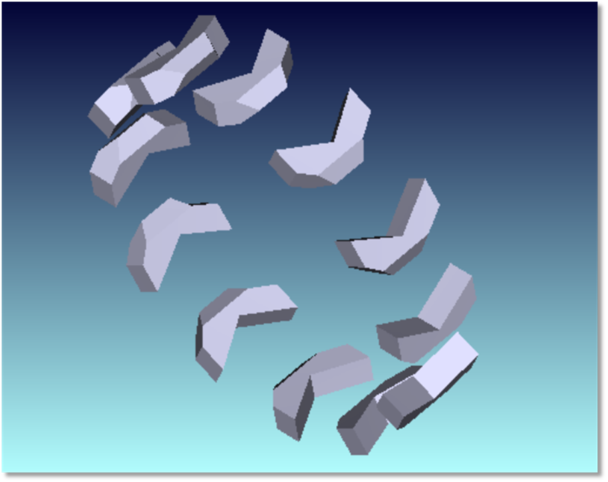
Mode 0: The sketches for this mode are based on the sample file"Zemax\Samples\Non-sequential\Geometry Creation\Ring Array Example 2- Spiral of Archimedes.ZMX"
The parent object is first placed at the vertex of the Array Ring.
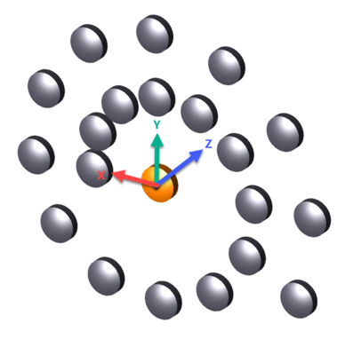
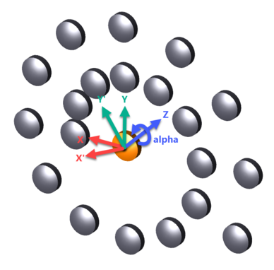
The object is then rotated around the array local +Z axis by the angle α.
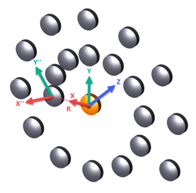
The object is then shifted along the array local +X axis by the distance R.
The object is then rotated around the array local Z axis by the angle γ. This is the position of the first element in the array.
Note that the following image demonstrates a γ value of 35 degrees, whereas the sample file "Ring Array Example 2- Spiral of Archimedes.ZMX" has a γ value of 0 degrees. The difference is for the purpose of demonstration.
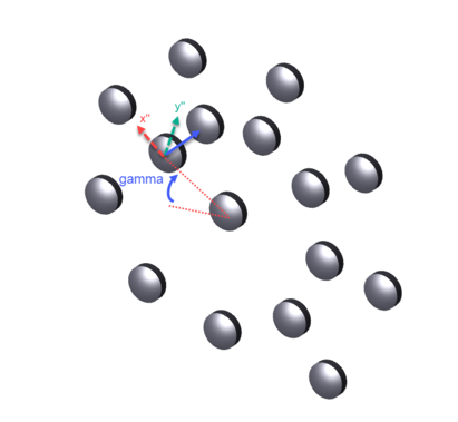
Subsequent array elements are further rotated around the array local Z axis by an angle ẟ /N. The angular position of the array element "k" is given by θ = γ + k* ẟ /N, where k varies from 0 to N-1. For a complete ring, ẟ should be 360. Mode 0 may also be used to form a Spiral of Archimedes, where R is replaced by R + k* β * ẟ /N and β is interpreted to be in lens units per degree. The value ε in lens units may also be used to define a step change in R every time the angle given by k* ẟ /N passes 360 degrees. Ray tracing will generally be much slower when either β or ε are not zero, since the symmetry of the array is broken.
Mode 1: The sketches for this mode are based on the sample file "Zemax\Samples\Non-sequential\Geometry Creation\Ring Array Example 1- Fly's Eye Array.ZMX"
The parent object is first placed at the vertex of the Array Ring.

The object is then rotated around the array local +Z axis by the angle α.
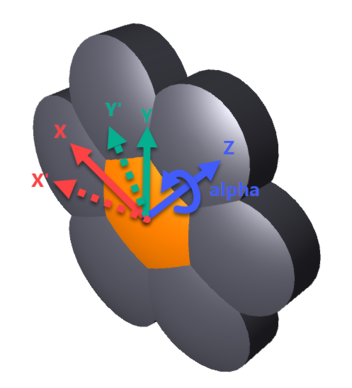
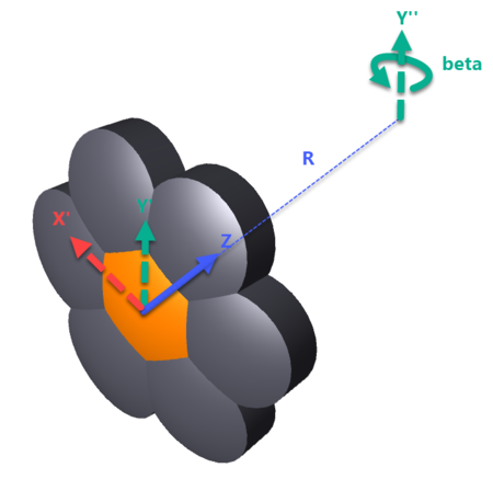
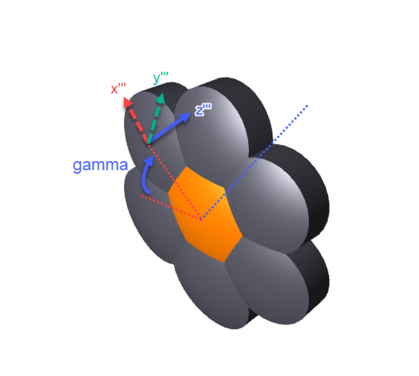
The object is then rotated an angle β about an axis parallel to the array local Y axis that is shifted by R in the array local +Z direction, so the array element's local Z points toward the center of a sphere with radius R (or away from the center if R is negative). The sign convention for the angle β used here is that β is always positive, and the object is always rotated toward the local +X axis, whether or not R is positive or negative.
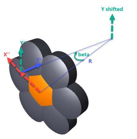
The object is then rotated around the array local Z axis by the angle γ. This is the position of the first element in the array (k = 0).
Note that the following image demonstrates a γ value of 30 degrees, whereas the sample file "Ring Array Example 1- Fly's Eye Array.ZMX" has a γ value of 0 degrees. The difference is for the purpose of demonstration.
Subsequent array elements are further rotated around the Z axis by an angle ẟ /N.
The position of the individual elements in the array can be calculated with the following equations:


For all modes, to form a complete ring, ẟ should be 360. Smaller values of ẟ will form an arc of objects. Larger values of ẟ may cause elements to overlap, which may create an invalid geometry. The angle γ "clocks" the starting point of the ring or arc around Z.
Most properties of the Array Ring object are defined by the parent object. The exceptions, which may be distinct for the Array ring object and the parent object, are the "Rays Ignore This Object" and the "Do Not Draw Object" settings. All other properties, including face definition, material, coatings, scattering, diffraction, or gradient index properties, are as defined for the parent object, and the array object settings will be ignored. If the parent object is not needed, use the "Rays Ignore This Object" and "Do Not Draw Object" settings on the parent object (See "Type Tab" and "Draw Tab"). The array will still be created and ray traced even if the parent object is not drawn or ray traced. Note that rays striking an array object will report hitting the parent object number, not the array object number. For this reason, when using ZRD files, optimization operands, or filter strings, the object number used to refer to ray data should be the parent object number.
When nesting array objects inside or outside other objects, the usual nesting rules apply. For more information see "Nesting volumes". However, it is the placement of the parent object in the NSC Editor, and not the array object, that determines the nesting rules. Specifically, if an array object is to be nested inside of another, outermost object, the parent object must follow the outermost object in the editor.
Next: