
Adding a 3D Layout Component
Use the following procedure to add a layout component to a Maxwell 3D design. These instructions assume that an HFSS 3D Layout of the PCB to be analyzed already exists.
- In the Project Manager, right-click 3D Components and from the shortcut menu, select Browse Layout Component > one of the following options:
- Import .aedbcomp file: Choose this option if you have exported an HFSS 3D Layout as a single-file Layout Component (*.aedbcomp). A Select layout component file to import dialog box appears in which you can browse to the file location and select and open it.
- Browse to project aedb folder: HFSS 3D Layout design files are stored in a folder named <Project_Name>.aedb. If the source project contains more than one design, the design name will also be included (<Project_Name><Design_Name.aedb). When you select this option, the Select aedb folder to import dialog box appears. Navigate to the desired folder, double-click it to display its top-level contents, and click Open to select the folder.
- Insert Existing EDB Definition: This option will only be available if you have already imported at least one layout into the currently active mechanical design. Any such layouts will appear in a flyout menu, and you can click the one you wish to insert into the model.
- Perform the following steps within the General tab:
- Optionally, change the Component Name from its default value (LCx, where x is an automatically incremented serial number).
- Choose the Target Coordinate System on which to base the layout component placement. Relative coordinate systems, defined in the target design prior to starting the Browse Layout Component process, appear in the drop-down menu in addition to the Global CS.
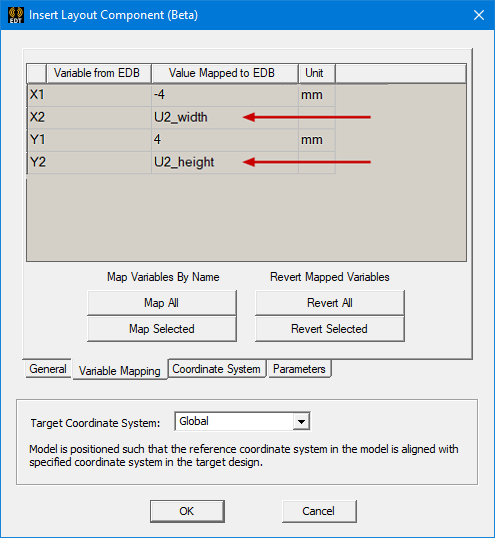
- Select the Variable Mapping tab.
- If there are no applicable variables in the source layout, no variables will be listed in this tab, and you can skip to step 4.
- When applicable variables are present in the source layout, they are listed on this tab, and the following actions are possible:
- Optionally, you can substitute a different numerical value or substitute variables (instance parameter names) for the numeric values in the Values Mapped to EDB column. This substitution is particularly useful if you wish to include multiple instances of the layout component in a single design and have geometry variations between the instances. See Instance Variation for more information. Additionally, you can use variables to manipulate the geometry during an optimization or parametric analysis.
- Alternatively, you can use the following buttons to automate the variable mapping task or to revert to the original values:
- Map All: For all source layout variables, this command creates instance parameters, each with the same name and value as the source variable.
- Map Selected: For selected layout variables, this command creates instance parameters, each with the same name and value as the source variable. Before clicking the Map Selected button, click a table row to select a variable to map. Ctrl+click to select multiple variables or to toggle the selection state of a row.
- Revert All: For all variables, this command reverts the Value Mapped to EDT entry to the original source layout value.
- Revert Selected: For selected table rows, this command reverts the Value Mapped to EDT entries to the original source layout values. Before clicking the Revert Selected button, click a table row to select a variable to revert. Ctrl+click to select multiple variables or to toggle the selection state of a row.
- In the Coordinate System tab, select a coordinate system from layout to serve as reference for component placement. You can allow include or exclude parts of the layout.
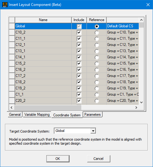
Layout component import supports relative CS placement, move, rotate, etc. Once imported, the layout ports will be created in the Project Manager tree. The bounding box and ports have actual Maxwell 3D geometry, but any visible object will have snapping locations when in snap mode or when creating a CS.
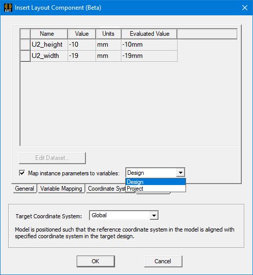
- Select the Parameters tab.
- Optionally, toggle the selection of Map instance parameters to variables as preferred.
-
If the Map instance parameters to variables option is selected, choose either Design or Project from the adjacent drop-down menu to specify the type of local variable to create.
As previously stated, the variable name will be prefixed with a dollar sign ($) automatically when you choose to create local Project variables.
- Click OK.
-
Optionally, you can change the visualization characteristics of the layout component; see Visualization for Layout Components for more details.
-
In object selection mode, select all layers of the layout component and assign a length-based mesh operation on the selection. Set the maximum element length to be three to four times the width or height of the grid cells, whichever is the lesser.
If a layout component has previously been added to the active mechanical design, the project name will be listed in the flyout menu, even if the component has since been deleted. You can select the project name from this flyout menu to re-add the component to the design. If you were to select it while the component already exists in the design, a duplicate layout component, overlapping the original one, would be added. Therefore, avoid doing so unless you want a duplicate component and plan on moving it to a separate location. You can also define a relative coordinate system (RCS) and choose to place the new component according to the RCS instead of dropping it on top of the previous layout component and then moving it.
Unused layout components that remain in the flyout menu can be removed by editing the Components Library. To do so, right click Components under Definitions in the Project Manager and choose Edit Library from the shortcut menu. Select one or more rows of the Components table and click Remove Component(s). Click Yes to confirm removal for each selected component entry. Finally, click OK to exit the Edit Library dialog box.
The Insert Layout Component window appears with its General tab displayed:
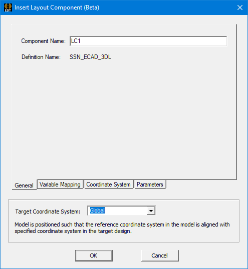
The Target Coordinate System setting is visible regardless of which window tab is currently selected.
What appears at this point depends on whether variables are defined in the source layout and are applicable to the current solution type. Choose one of the following two actions:
In-place definition of new variables is supported. If you specify a previously undefined variable name, the Add Variable dialog box will appear when you press Enter or advance to a different table cell so that you can define its unit type, units, and initial value.
In the following example, two of the four variables in the source ECAD database (X2 and Y2) have had instance parameters substituted for the original numeric values:
In the Parameters tab (next step), you can choose whether to create local Design or Project variables from instance parameters. For the latter type, the name will be automatically prefixed with a dollar sign ($) when the local variable is created. Therefore, you do not have to manually include a dollar sign at the beginning of the name you type.
If the original layout design includes additional CS, these are included as properties to the layout component in Maxwell 3D. As you select the original layout design to import to Maxwell, you can choose a custom coordinate system as the reference CS. After creation in Maxwell, you can choose a target CS for the layout component, and the component will be moved to a place where its reference CS snaps to the target CS or you can move the layout component using the snapping locations; see Editing the Placement of a Layout Component for more details.
If you chose not to define local variables in the Variable Mapping tab, or if the source design contains no variables, none will be listed in the Parameters tab. Skip to step 6.
Otherwise, when you have defined local variables in the Variable Mapping tab, they will be listed in the Parameters tab along with their values and units.
The following figure shows the parameters with two local variables substituted for numeric values (as shown in the preceding figure):
You can choose whether to keep these mapped variables only as instance parameters or to also create local Design variables or Project variables, as follows:
Alternatively, if you also wish to include the mapped variables as Maxwell design or AEDT project variables, select this option and choose between the two types in the next step.
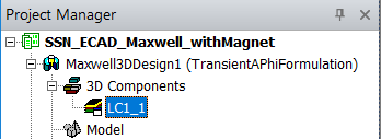
The layout component name appears under 3D Components in the Project Manager. An instance number ("_1" in this case) has been appended to the component name:
Typically, you need not enforce the maximum element length inside the selection. For the majority of printed circuit boards, there will only be one element through the thickness of any layer due to their thinness. For more information on meshing layout components, see Meshing Recommendations for a Layout Component.