
Simulating a 3D Layout Component with an A-Phi Solver
With the Transient or AC Magnetic A-Phi solver, Maxwell 3D can run an analysis that includes a 3D layout component. This feature makes it easier to simulate electronic applications such as multilayer PCBs to calculate the Lorentz force due to trace currents and external magnetic fields.
Running an analysis on a design with a 3D layout component requires the use of both HFSS 3D Layout and Maxwell 3D products. You first create the layout component with excitations, mesh operations and RLC components defined in HFSS 3D Layout. Then, you must import the component in a Maxwell 3D design. Maxwell will automatically import the layout excitations and circuit components (RLC). You need to select the type of the excitations (voltage or current), and enter certain information related to each excitation type. The rest of this section will explain the details of the entire design flow of a Maxwell design with the 3D layout component.
Creating a Layout Component in HFSS 3D Layout
You can either create a component from scratch or can import third-party layout design data (Refer to Importing Layout Design Data in the HFSS 3D Layout help). You can use all capabilities of the Layout Editor such as geometry check, shorts/opens in a design.
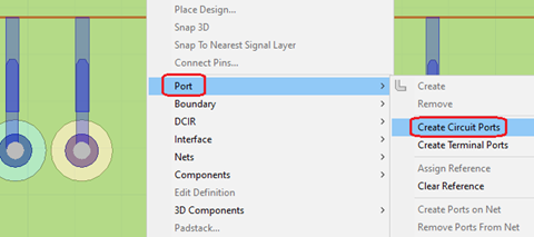
You need to define excitations in the Layout design by creating circuit ports. Existing port definitions are still valid ( refer to Circuit Ports and Elements in the HFSS 3D Layout Help). In the Layout Editor, one way to create a circuit port is to right-click the geometry view, select Port > Create Circuit Ports, select two points, and then select a Positive Terminal Layer and Negative Terminal Layer in the pop-up dialog box.

You can add lumped circuit elements into the design. For RLC support, you define a component for each lumped element (R, L, or C). The component has two pins and associated padstacks. Each component must have only one lumped element type (enable only one, as shown). Note that serial or parallel connection of RLC is not supported, so Maxwell will ignore the Type selection.

Mesh operations for the layout design should be defined in the layout. To assign mesh operations, first add an HFSS solution setup. Then right-click the solution setup and select Assign Mesh Operation:


In the Select Geometry dialog box, you can specify the Max Length to refine the mesh. Note that the solution setup is not used for the solution of the design.

Once the design is complete, you can save it as a component or just save the layout design. When the component is imported in Maxwell, the design data including layout model (with virtual geometry view), excitation assignments, mesh operations, RLC data, and materials will be automatically imported into Maxwell. Pin groups are imported as excitations, but the pin group information is still available for simulation.
Importing a Layout Component to Maxwell 3D
To use a 3D layout in the Maxwell solver, you must import it. For information about importing a layout component into Maxwell, see Adding a 3D Layout.
Once you have imported a 3D layout, you can view object attributes: click Object Attributes in the component property window.
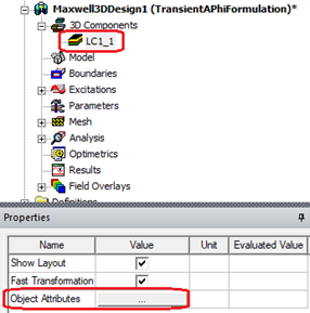
In the Object Attributes dialog box, you can view object attributes such as: Name, Material, Type, and so on. There are different display modes: Layer, Net, and Object. In the Show column, after changing the object visibility, you can see the checked objects in the geometry view by clicking Apply button. See Visualization for Layout Components for more details.

You can modify the Layout component. To edit the layout, right-click on the component, and select Edit Layout... This will open the layout design of the component in a new project. You can then modify the design in the new project. Once the modified design is saved, Maxwell will automatically update the layout component.

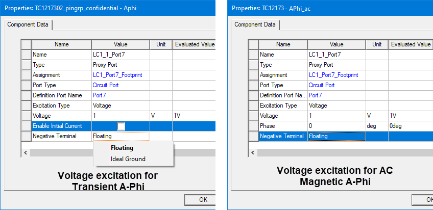
After a layout design is imported into Maxwell, the layout circuit ports will be converted into a Proxy Port in Maxwell. Each proxy port has two nodes. One node is positive (current flows into the conductor), and the other one is negative (current flows out of the conductor). A node can be a terminal or a pin group (group of terminals). All terminals of a pin group are parallel connected, so they have the same potential value. Maxwell treats a terminal as an equipotential surface. Examples of port definitions are shown below:

Port excitation data can be modified for different excitation types. The Excitation Type can be Voltage or Current.
- For voltage excitation, enter a voltage value (and a phase value for AC Magnetic A-Phi), and select the behavior of the negative terminal (Ideal Ground or Floating). The default is Floating. The solver applies the specified voltage value (and the specified phase value for AC Magnetic A-Phi) as a potential drop between the terminals. If Ideal Ground is selected, the negative terminal potential is set to 0 V. For Floating, the negative terminal potential is unknown. For the transient solver, you can also specify the initial current value by selecting Enable Initial Current.
- For current excitation, enter a current value (and a phase value for AC Magnetic A-Phi), and select the behavior of the negative terminal.
For a Maxwell design with a 3D layout component, the Phi Plus mesher setting is available in the Maxwell 3D > Mesh > Initial Mesh Settings dialog box; it replaces the TAU mesher, which will be grayed out.
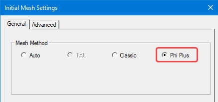
You can continue to use existing mesh operations for non-component objects. The suggested mesh method is Phi for a layout component. You can specify this in the Maxwell Initial Mesh Settings, see Meshing Recommendations for Layout Component for more details.
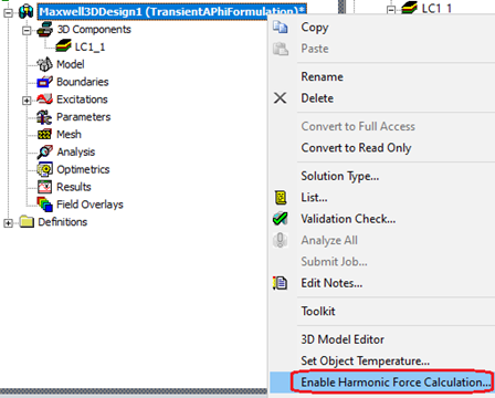
To calculate harmonic force on objects, right-click the design, then select Enable Harmonic Force Calculation...
In the Enable Harmonic Force Dialog window, on the Layout tab, you can select one layout component from the Layout component drop-down menu, and select <layer, net> pairs in the following grid, each <layer, net> pair represents the object(s) in the intersection of corresponding layer and net.

To calculate Lorentz force on objects, right-click Parameters, and select Assign > Force from Layout... Note that this menu item will only be available if there is a layout component.

In the Layout Force Setup window, on the Force tab, select one layout component from the Layout Component drop-down menu, and select <layer, net> pairs in the following grid. Each <layer, net> pair represents the object(s) in the intersection of corresponding layer and net. Then select the postprocessing coordinate system on the Post Processing tab.

The LayoutForce can be plotted from the reporter as shown below:

Layout force can also be viewed in the Solution Data window:

Mesh Statistics for layout objects can also be viewed in the Solutions window:

To review results from the Field reporter, you can select the layout objects in the Create Field Plot window:

Limitations for the 3D Layout Component Feature in the Maxwell Solver
- Field calculator for expression cache/output variables can only be setup after solving.
- Conduction path functionality in Maxwell is not applicable to layout component.