
Parametric Array Antennas for SBR+ Solution Type
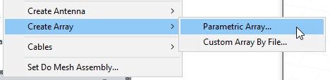
For SBR+ solution type, you can access a range of parametric array antennas via the Project tree 3D Components icon right-click menu option, under Create Antenna.
As with other Parametric antennas Parametric Array antennas are antenna sources that either have no physical structure definition or a highly idealized physical structure. No model parts are constructed or used in the simulation. They create far-field pattern or current distribution sources that can provide S-parameter outputs and composite far-field radiation patterns.
Parametric Array antennas are very quick to define and place, copy and duplicate, and are thus intended for systems studies where the specific antenna structure is either unknown or a simple, topologically representative antenna type is sufficient. The editable parameters depend on the antenna element type.
When you create a Parametric Array you specify General definition properties for the array, which includes the type of antenna used for the array elements by selecting from the fourteen existing parametric antenna types. You also have options for Element Rotation, Element Offset and Conformance to Geometry. The array definition includes settings to configure the Geometry layout that specifies the overall size of the array and spacing of the array elements, and various other geometry configuration options for how the individual antenna elements are placed within the array. Several Weighting operations and functions for the individual element contributions to the array are also specified with the definition, including beam steering, edge taper functions, sum/difference patterns, etc.
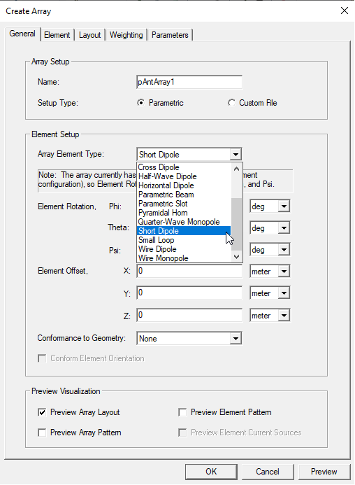
In addition to the 12 predefined parametric antenna types, there are three additional ways to specify the antenna element type for the array: 1) an external file with a far-field pattern, 2) an external file with a near-field pattern, and 3) link to another HFSS source design that provides (either by definition or by solution) a suitable excitation source for SBR+ (radiation or FEBI boundary, etc). Note that in terms of the antenna elements, these parametric antenna arrays are uniform, meaning they are defined with the same antenna type for all elements of the array. When a File Based Antenna is selected as the Array Element Type, the SBR+ solver will automatically interpolate the source fields from the file-based antenna in order to represent the antenna at all frequencies of the user defined frequency sweep in solution setup. The file-based antenna requires at least two frequencies, and the min/max frequencies of the user defined sweep should fall within the frequency band of the file-based antenna.
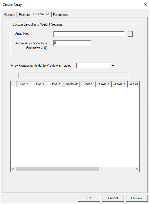
If you select Create Array > Custom Array by File... the Create Array window opens with Custom File selected.
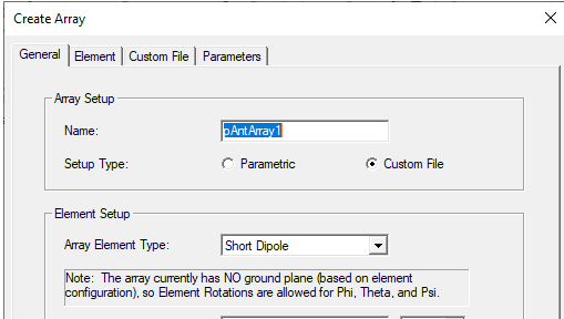
This dialog includes a Custom File tab that lets you specify a custom array layout geometry and weighting via an external file format, the “*.sarr” format from EMA3D. The array element positions, orientations, and complex weights are specified in this file format. The complex weights can be specified over a set of frequencies and specified “states” which are indexed across all elements.
After being created, the parametric array model is listed under the Project tree under 3D Components and automatically includes a port to support S-parameter output. The generated port is shown under Excitations, and the port post-processing setting can be modified from the Properties window when this port is selected.
![]()
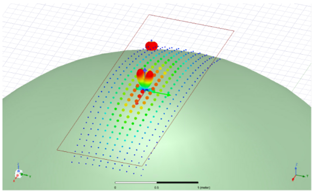
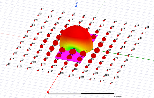
Selecting the antenna under 3D Components causes the Properties window to display with tabs for General antenna Properties and Visualization settings. In the model window, the scaled far field pattern of the antenna array can be displayed at the array origin. In addition, the far field pattern or current source representation (for a near field antenna) of an individual element can be displayed at a specified element number.
In the model window, the scaled far field pattern of the antenna array can be displayed at the array origin.
The array definition will consist of a geometry layout that specifies the overall size of the array, type and spacing of the array elements, and various other configuration options for how the individual antenna elements are placed within the array. The array definition also provides methods for weighting the individual element contributions to the array, including beam steering, edge taper functions, sum/difference patterns, etc.
Using with Other SBR+ Features
Power specification
A Parametric Array by default is treated like a single antenna, and Edit Sources defines a total input power as a composite port. All analysis options including coupling, far- and near-field analysis, wedge corrections (PTD/UTD), and Creeping Wave are available. The Parametric Arrays do not analyze their element couplings and are assumed to have efficiencies as same as their element antenna. Results are normalized to radiated power to align with the Antenna Parameters.
On the other hand, you may select Use Per-Element Power Specification for Parametric Array in Edit Sources when only a Parametric Array exists in the scene.

When you select the option, Edit Sources defines the input power of an element before applying the Aperture Taper configured in Array Weightings. The Parametric Array with this option gives results similar to HFSS post-processing feature of Antenna Array and coupling analysis and Enhanced Radiated Power Accuracy are not supported.
Visual Ray Trace (VRT) plots for Shooting-Bouncing Rays (SBR) Creeping Wave (CW) rays are available via Field Overlays. Parametric arrays can be specified as the VRT “launch from” object/location for SBR plots. For parametric antenna arrays, the array centroid or an array element # can be specified as the “launch from” location.
There are 2 primary workflows described below: the first is for creating and using parametric antenna arrays in an SBR+ simulation, and the second is for creating visual ray trace (VRT) plots for SBR rays. The summary workflows (no screenshots or detailed explanations) are described first, followed by both of the more detailed workflows.
Limitations:
After they are created, parametric antenna arrays appear as a single port in the source excitations. Since the arrays are analytically defined, their individual element ports are not available for separate analysis. This means that in the “Select Tx/Rx” matrix and “Edit Sources” configuration dialogs these parametric antenna arrays appear as a single composite antenna/port for the whole array. In addition, the only source context available for reports and post-processing will be the single composite port for the array.
The outputs from SBR+ simulations with parametric antennas include:
- S-parameters.
- Composite far-field radiation patterns.
- Incident field reporter outputs provide the free space radiation patterns of the antenna.
Prerequisites
- The Solution Type must be SBR+.
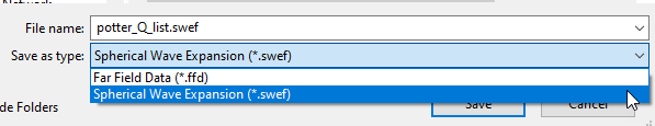
- If you use a File-based parametric antenna, it must be defined with at least two frequencies whose min/max meet or exceed the extents of the simulation frequency sweep. A file-based can be in far field wave format, .ffd, or, for Spherical Wave Expansion Import, you can import .swef format files.
Primary Workflows for Parametric Antenna Arrays
There are three primary workflows for using Parametric Antenna Arrays in the SBR+ solution type: