Parametric Antennas and Parametric Array Antennas for VRT Plots
This chapter provides a summary workflow, and a detailed workflow for using Parametric Antennas and Arrays to create Visual Ray Traced plots with SBR rays and creeping wave (CW) rays. Any Antenna to be used with VRT must be created as a 3D Component in HFSS for it to be available as a ray launch source. Note that VRT plots for creeping wave (CW) rays are only supported for Antennas that can be represented (either synthetically or parametrically) by current sources. This means that far-field antennas created either via external file or via linked design cannot be used with CW plots, but they may still be used for SBR plots.
Summary Workflow
-
Open/create a project with an HFSS design having SBR+ solution type, and containing either a parametric antenna or parametric array antenna component.
- Add a VRT plot for SBR by selecting Plot VRT > SBR from the right-click menu for the Field Overlays icon in the Project Manager window.
- In the Create SBR VRT Plot dialog
- From the “Launch From:” combo box list, select “Antenna”
- From the “Antenna/Port:” combo box list of available antennas, select the desired antenna source to use for launching SBR rays
- If the selected Antenna is an array, select the desired array element number from where rays will be launched
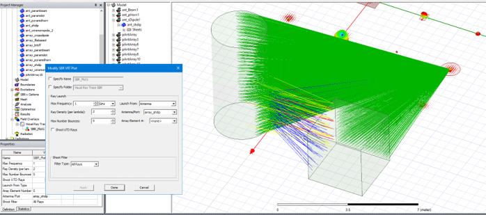
- Observe the resulting set of SBR rays generated in the 3D model window
Detailed Workflow
- Open/create a project with an HFSS design having SBR+ solution type, and containing either a parametric antenna or parametric array antenna component. Remember the design must contain some model geometry so the Visual Ray Trace (VRT) plot will produce rays.
The design(s) should also contain some SBR+ geometry so the Visual Ray Trace (VRT) plot will produce rays.
- Add a VRT plot for SBR by right clicking Field Overlays in the Project Manager window and selecting Plot VRT > SBR.
This opens the Create SBR VRT Plot dialog.
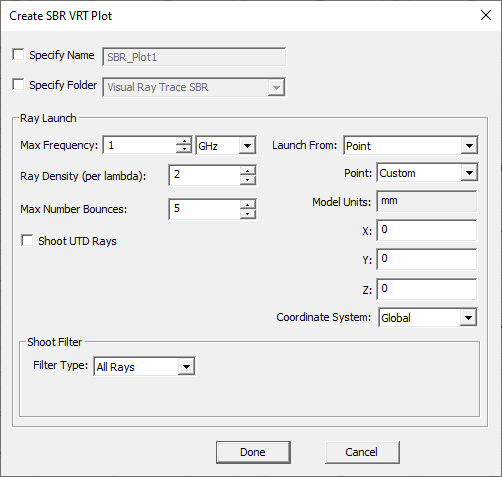
- In the Create SBR VRT Plot dialog:
- From the Launch From: combo box list, select Antenna.
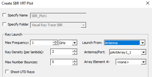
This enables the Antenna/Port: combo box list of available antennas.
- Select the desired antenna source to use for launching SBR rays.
- If the selected Antenna is an array, select the desired array element number from where rays will be launched.
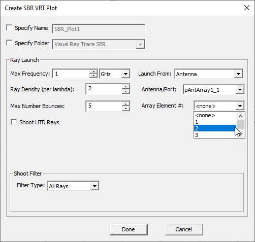
If you select <none> for the Array Element #, then the rays are launched from the placement location of the antenna (the origin of the antenna local coord sys) instead of from a specific array element location
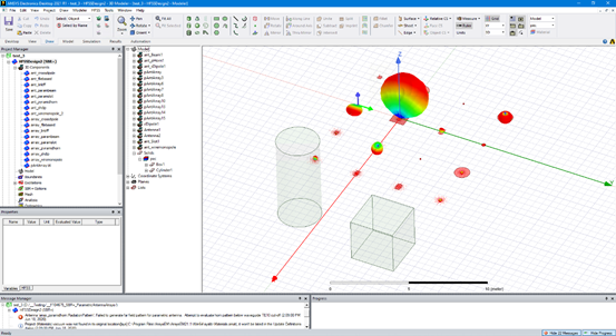
- Observe the resulting set of SBR rays generated in the 3D model window.
The steps for creating a VRT plot for CW rays with a parametric array antenna are nearly identical to the steps for a VRT plot showing SBR rays. See the page on Creeping Wave for Antenna Placement on Curved Surfaces in SBR+ Simulation for more details on the setup of a VRT plot with CW rays. As with an SBR plot, the CW plot may be configured to launch rays from a specific element number of the array antenna. Note that for CW plots with parametric array (and for CW analysis setup with parametric arrays), surface conformance of the array elements is typically required to produce suitable CW results.
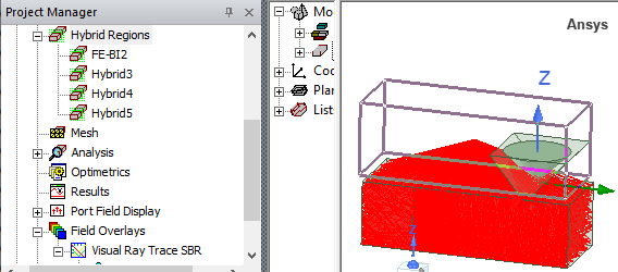
Note: In the case of a FE-BI Hybrid Region, by design the VRT rays launch from the center of the FE-BI, rather than a port location in the FE-BI portion of the design. For example, in the following image, the highlighted box is assigned as a FE-BI Hybrid Region, and the center of the box becomes the VRT launch point rather than the antenna within the Hybrid region.