Using the Layout Component’s Reference CS for Placement
When importing the layout component, it is important to consider which CS to set as reference. If you do not carefully consider the layout's reference CS in relation to the target CS, you will not get the result you expected. This is best explained with the following example.
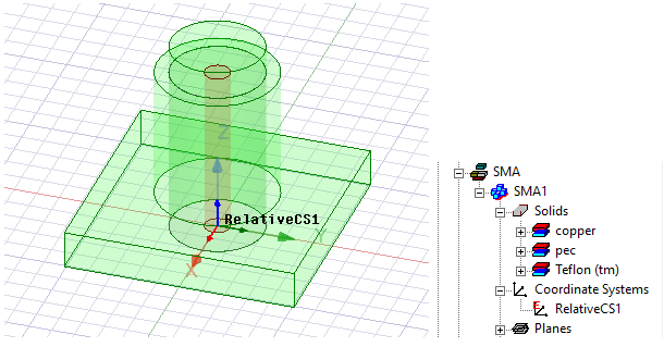
A 3D component (shown in green) comes with a CS called “RelativeCS1”. This CS is located at the bottom of the component and at the center of the internal cylinder structure.
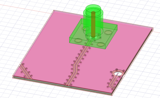
We also have a layout component, shown in pink. In the original layout design of this component, the global CS is located at one of the corners of the entire structure.
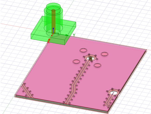
In this example, you want to place the layout component under the 3D component so that its holes (in the middle of the component) are aligned with the hole from the 3D component. When you import the layout component in Maxwell using its global CS as the reference CS and “RelativeCS1” as the layout component’s target CS, it snaps the layout component’s global CS to the target CS, which will look like the figure below.
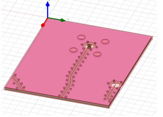
In the original layout design, there is another CS at the center of the holes called “CS_1." When you import the layout component, select this new CS as the reference CS.
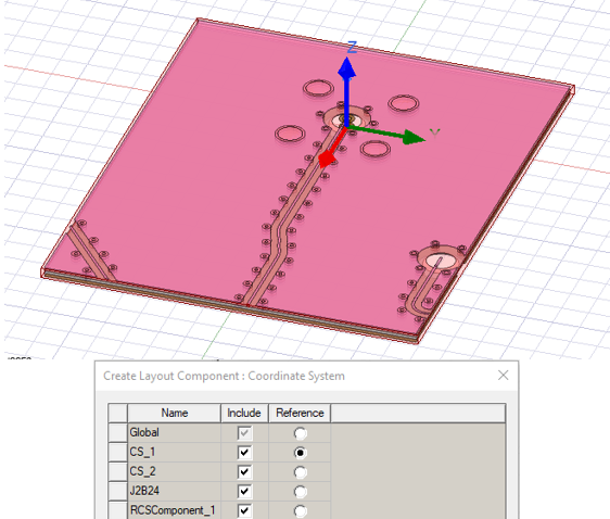
The layout component is now in the right place where its reference CS “CS_1” snaps to the target CS “RelativeCS1.”