
Surface Roughness for SBR+
HFSS SBR+ provides the option to simulate the scattering impact of surface roughness applied to object boundaries. The surface roughness model includes two additional physical effects into the SBR+ simulation: coherent field attenuation and diffuse incoherent scattering. These effects are wavelength dependent. As the surface height deviations become large relative to the simulation wavelength, coherent specular reflections are converted into a diffuse response that has an incoherent (random) phase.
The SBR+ model characterizes surface roughness as a random process which is defined by two parameters: 1) the standard deviation of surface heights (H), and 2) a surface correlation length (L).
The surface height deviations are modeled as a Gaussian distribution with mean zero and standard deviation H. The surface correlation (i.e., its auto-correlation function) is also assumed to follow a Gaussian distribution with standard deviation  . The correlation length L may be thought of as the average lateral distance between neighboring peaks on the surface.
For user inputs, the correlation length is replaced with a dimensionless parameter called roughness, which is defined as R = H / L. A roughness value of 0 produces a flat surface. The surface roughness increases with R and has typical values in the range [0.,0.5]. As the figure illustrates, the parameter R provides an intuitive measure of roughness that is independent of the magnitude of the height fluctuations (H).
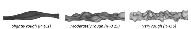
Figure: Explicit rough surfaces with different roughness values R and height standard deviation H=1mm.
Prerequisites
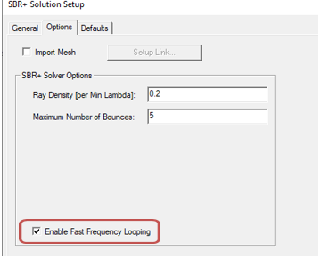
- The feature is for SBR+ Solution Setups with Fast Frequency Looping (FFL) enabled in the SBR+ Solution Setup Options. If FFL is not enabled, an error message is issued to the Message window.
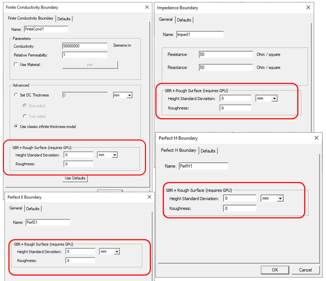
- The roughness model may only be applied to non-penetrable surface boundaries: Perfect E, Perfect H, Layered Impedance (one-sided), Impedance Boundary, and Finite Conductivity.
- The SBR+ rough surface model requires GPU acceleration to initialize the model. If this criteria is not met, an error message is issued during SBR+ pre-processing. An HPC license is not required to enable the model.
Setting up an SBR+ Simulation with Surface Roughness
- Create an HFSS design and set the Solution type to SBR+.
- Add geometry objects.
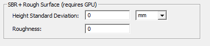
- Assign object boundaries. For the Finite Conductivity Boundary, Impedance Boundary, Perfect E Boundary and Perfect H Boundaries, you can set the SBR+ Rough Surface properties as shown. Typical values for rough asphalt are H=1mm for height deviation, with a roughness of R=0.2 so the corrolation length L = 5mm.
For the Layered Impedance Boundary, select the Layers tab and select One sided and edit the properties under the “SBR+ Rough Surface for Top Layer” panel.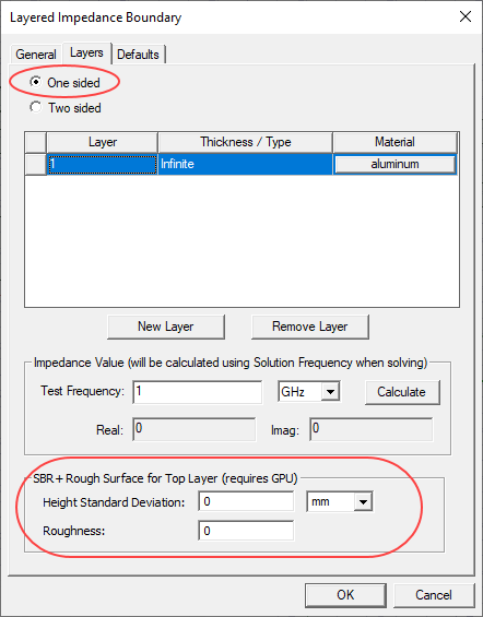
- The “SBR+ Rough Surface” properties can also be edited after creating the boundary by selecting the boundary in the project tree and editing values in the property window.
- Add an excitation, such as Parametric Antenna under 3D components.
- In the “Options” tab of the “SBR+ Solution Setup” dialog box, select “Enable Fast Frequency Looping”.
- Run validation
- Run simulation