
Assign Wave Ports for Terminal Solutions
A terminal is a geometry intersection of a conducting object with a port face. The intersection can be a face or an edge in a conducting geometry. The edge can even extend outside the port and though it can be defined as a terminal in the user interface, only the portion of the edge that overlaps with the port is used to define the terminal edge for the solver.
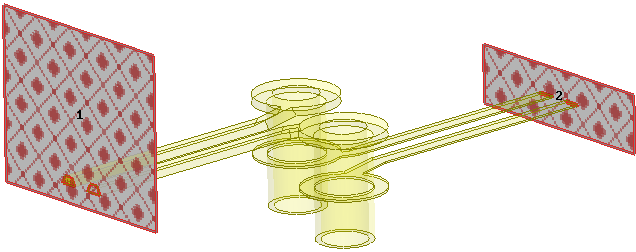
In this section we will assign wave ports on a differential pair via model shown below.
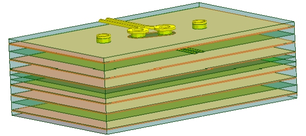
We will assign a microstrip port and a stripline port. The guidelines for defining port size introduced in the Microstrip Waveguide section are also applicable for the differential pair model. The microstrip port size is defined as (10w+s + 2w) x 8h where w = microstrip trace width, s = separation between the traces, and h = height of the substrate.
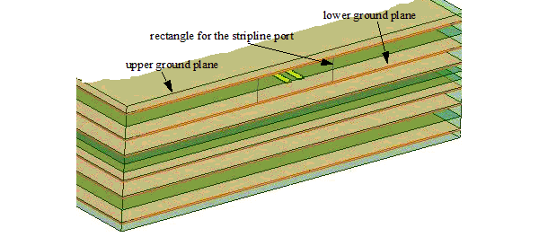
The stripline port is defined as (10b + c + b) x d where b = stripline trace width, c = separation between the traces and d = the distance between the upper and the lower ground plane.
Perform the following steps for terminal assignment.
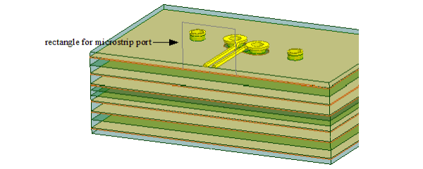
- Right-click the rectangle for the microstrip
port and select Assign Excitations>Wave Port.
The Reference Conductors dialog box appears.
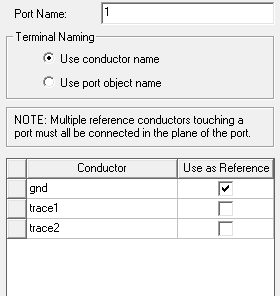
- Select the gnd
conductor as reference and click OK.
Note:
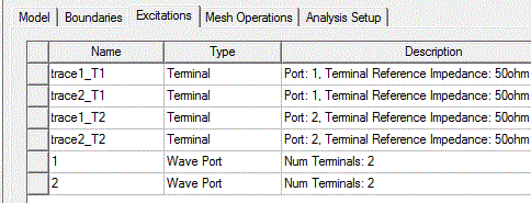
Number of terminals = Number of conductors - 1 = 3-1 = 2.
The port gets assigned and the terminals appear automatically on the microstrip.
- Similarly assign a wave port on the stripline rectangle.
The port gets assigned and the terminals appear automatically on the stripline.
Note:- In rare cases when automatic terminal assignment fails, you can manually assign a terminal by selecting the face of the conductor.
- Identification of conductors depends on a threshold conductivity value. The threshold is based on the material assignment or the boundary assignment if a conducting boundary is assigned to the object.
- The project manager window gets populated as shown in the following figure.
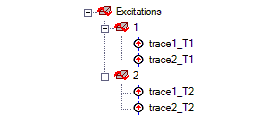
Terminal naming conventions are based by default on the first geometry in the assignment selection for the terminal. You can change the names from the Set Default Boundary/Excitation Base Name dialog box. For auto assign terminals, you can also specify whether naming uses the conductor or the port object name.
Multi-Select Ports and Terminals
To view all of the assigned excitations at the same time, perform the following steps:
- Double-click Excitations
from the Project Manager window.
This brings up the Design List dialog box.
- Press Ctrl
and select the excitations that you want to see in the model.
The selected excitations get highlighted in the model.
- Click Done
to close the dialog box.
For example, the following figure shows all the excitations on the differential pair.
Automatic PEC Creation on Terminal Wave Ports
In HFSS, A wave port must have 'solve inside' objects on one side only. An internal wave port would require a PEC object to be attached to and cover the opposite side before the solution can proceed. This HFSS Boundary Assignment Option automatically adds a PEC backing to every newly created wave port when necessary. When a new wave port is created and requires a PEC backing, a dialog window opens to let users create such backing by extruding the port face with specified thickness. You have the option to flip the side of the PEC backing. You can also set the thickness as a variable.
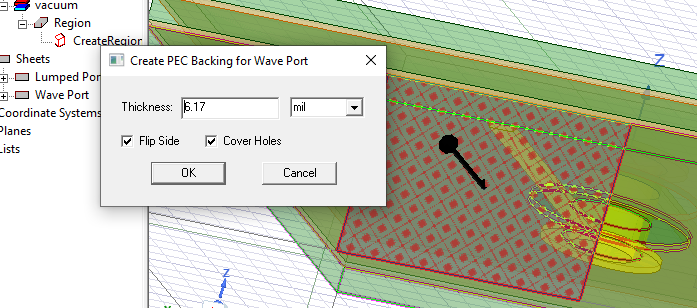
After clicking OK, the PEC backing is created and the new PEC object appears in the History tree.
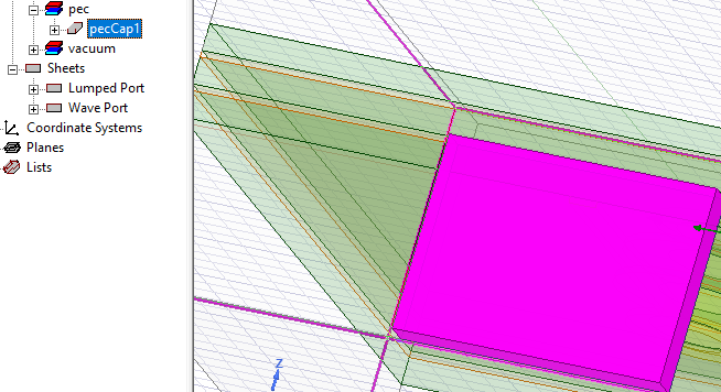
Once the PEC cap is created it is associated with the port. If you edit the geometry of the port or the geometry/material of the cap, association is deleted and a message is issued. If you reassign or delete the port, the PEC cap is deleted, and a warning is issued.
For an example, see Automatic PEC Creation for Wave Ports.