Wave Port Size
Wave ports are used for exciting transmission lines and waveguide structures. Wave ports that are assigned on waveguide structures are naturally defined by the cross-section of the waveguides. However, for transmission lines (e.g., microstrip, CPW, slotline) ports should be defined carefully. Sometimes transmission lines are part of a large PCB structure which makes it your responsibility to define the port size properly. This section provides guidelines for the appropriate port sizes for transmission lines. Examples of different waveguide and transmission line structures are as follows:
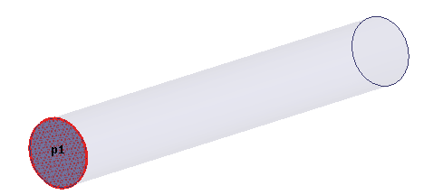
Circular Waveguide
An HFSS model of a cylindrical waveguide of uniform circular cross-section along its length excited with a wave port p1 is shown below. You do not need to define the port size because it is naturally defined by the cross-section.
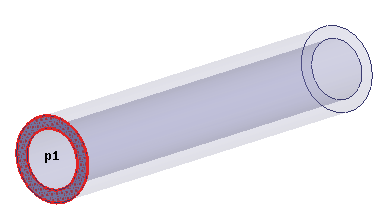
Coaxial Cable
The following figure represents a coaxial cable. You do not need to define the port size as it is naturally determined by the inner and outer radii of the shield.
Microstrip Transmission Line
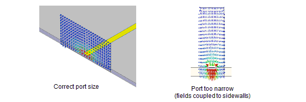
The figures below show an HFSS model of a microstrip transmission line and guidelines for setting the wave port dimensions.
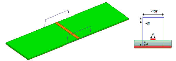
See the HFSS model at scale in the following figure. The bottom of the port touches the ground plane of the microstrip.

The port width affects the port impedance and the propagating modes. If the defined port is too narrow more fields will couple to the side walls. The height of the port is affected by the permittivity of the substrate. If the permittivity is too high less fields will propagate in the air, so the wave port can be made shorter.
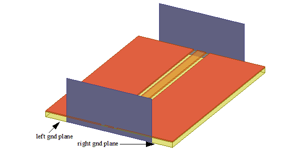
Coplanar Transmission Line
The following figure shows an HFSS model of a coplanar transmission line. The left and right edges of each port must touch the left and right ground planes. We recommend that you make the port size 8h x 10w where "w" represents the width of the trace and "h" represents the height of the substrate.