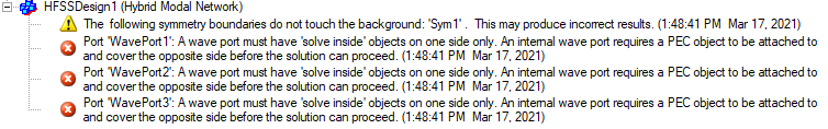
Automatic PEC Creation on Wave Ports
In HFSS, A wave port must have 'solve inside' objects on one side only. An internal wave port would require a PEC object to be attached to and cover the opposite side before the solution can proceed.
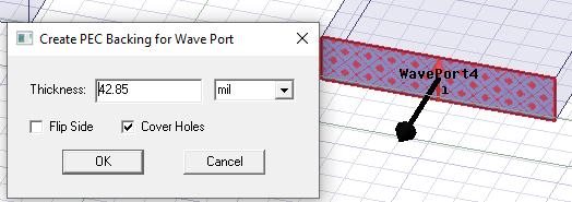
This HFSS Boundary Assignment Option automatically adds a PEC backing to every newly created wave port when necessary. When a new wave port is created and requires a PEC backing, a dialog window opens to let users create such backing by extruding the port face with specified thickness. You have the option to flip the side of the PEC backing. If the wave port has holes, you have the option to create backing that covers the holes. You can also set the thickness as a variable.
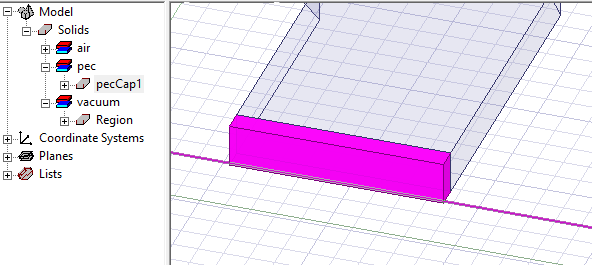
After clicking OK, the PEC backing is created and the new PEC object appears in the History tree.
Example Using the Waveguide Combiner Example
Open the HFSS example project “wg_combiner.aedt”. Add a region with padding around the design.
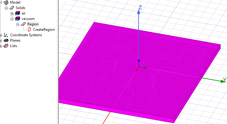
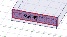
This will make all the wave ports internal to the design and invalid. Now delete one of the wave ports and create a new one on the same location, you will see this dialog after it is created.
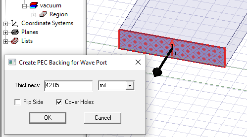
You can edit the Thickness and units. The black arrow on the selected wave port shows the side on which the backing is applied. If necessary, you can check Flip side to change the arrow direction. In this example, this is the correct side, so leave that unchecked. Click OK to see the PEC backing.
Validation will show that the other four wave ports are invalid and require PEC backing.