
Characteristic Impedance
2D Extractor can display a characteristic impedance (Z0) matrix for a transmission line. These matrices specify the relationship between voltages and currents on a multiple conductor transmission line.
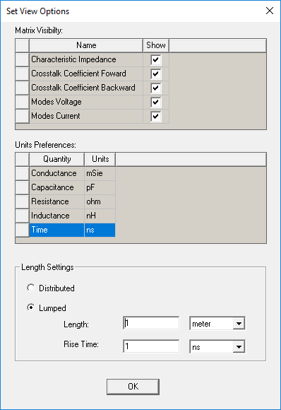
From the Set View Options window, you can select Characteristic Impedance.
Some important notes:
- You must solve for at least capacitance and inductance.
- Modal transformation matrices are used to decouple the lines in the problem. The Mode Data tab displays resulting values for the decoupled lines.
For a decoupled line, the software defines characteristic impedance as the following:

with values given in ohms. Thus, you must solve for both admittance and impedance.
Lossless Characteristic Impedance
For a decoupled lossless line, the software assumes that R ≪ jωL and G ≪ jωC (that is, losses are small), and defines
characteristic impedance as  with values given in ohms. When you design a circuit
using the model of a single transmission line, this is the appropriate
value to use as a resistance termination for that line.
with values given in ohms. When you design a circuit
using the model of a single transmission line, this is the appropriate
value to use as a resistance termination for that line.
The decoupled Zo values are used to compute the coupled characteristic impedance.
The matrix row and column headings are the conductor names.
For a set of coupled lines, the diagonal entries of the matrix (both approximately 91Ω here) are the appropriate termination values for both lines. The off-diagonal entries (both approximately 1.9 Ω here) give information about the crosstalk at the near end. The near end voltage on line i caused by a current in line j is represented by:

Thus, if line j carries 1 mA as it switches, there would be (1.9 Ω)(1 mA) = 1.9 mV of crosstalk on line i.
Lossy Characteristic Impedance
This displays the characteristic impedance for a lossy line. Characteristic impedance values are given as (R, X), where R and X are both in ohms. In this case, characteristic impedance is a complex number in the form Z0 =R + jX, where X is the reactance j(wL-1/(wC)) with w being 2p times the frequency (1kHz in the example) of the AC voltages during the solution.