
Viewing Matrix Data
To view matrix parameter data:
-
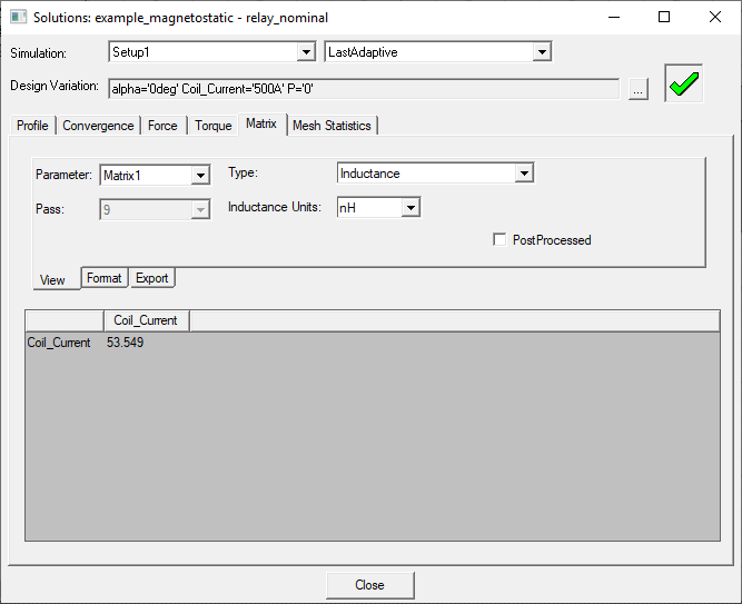
In the Project Manager tree, right-click the solution setup of interest, and then click Solutions on the shortcut menu.
The Solutions window appears. Select the Matrix tab. A typical example is shown below.
-
The Design Variation field shows the current design.
Optionally, click the ... button, and choose a design variation solved during an optimization or parametric analysis from the Set Design Variation window, which lists all the solved variations in the design.
-
In the Simulation drop-down menus:
- Select the solution setup from the left drop-down menu.
- Select the solved pass data you wish to view from the right drop-down menu, either the LastAdaptive pass or an intermediate AdaptivePass. If you select AdaptivePass you must also select the desired intermediate pass form the Pass drop-down menu.
- Select a Parameter.
-
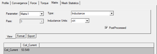
Select one of the items from the Type drop-down menu. Items available in the Type list depend upon the design’s solution type setting. For example:
- Inductance (for magnetostatic and 3D transient A-Phi solutions)
- Re(Z), Im(Z) (for eddy current solutions)
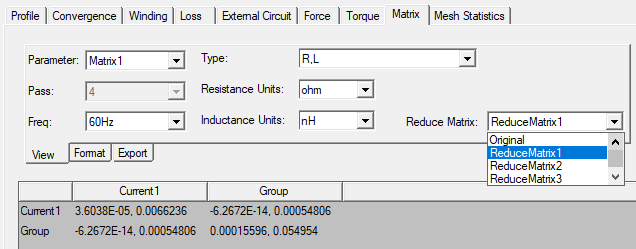
- R, L (for eddy current solutions. The extracted resistance values of designs that use Litz wire windings take into consideration the stranded AC loss effects due to skin effect and proximity effects.)
- G,C (for ACConduction solutions)
- Resistance (for 3D transient A-Phi solutions)
- Capacitance (for electrostatic and 3D transient A-Phi solutions)
- Conductance (for DC Conduction solutions)
- Flux Linkage (for magnetostatic and eddy current solutions)
- Inductive Coupling Coefficient (for magnetostatic and eddy current solutions)
- Capacitive Coupling Coefficient (for electrostatic and ACConduction solutions)
- Conductive Coupling Coefficient (for DC Conduction solutions)
Depending on the solution type you selected, you may have to specify the Units in which to display the information. The available units depend on the matrix type that is displayed.
The bottom pane displays values for the selected type. The Format tab allows you to customize how values are displayed by setting the desired width, precision, and whether to use scientific notation.
-
(Optional) For Magnetostatic designs, the results of the postprocessing calculation on the matrix, including grouped sources defined on the Matrix window's Post Processing tab, can be seen by selecting PostProcessed.
-
(Optional) For 2D and 3D Eddy Current designs, you can join (group) two or more excitations to one excitation in either a series or a parallel connection. The result of each set of join (group) operations is known as a Reduce Matrix. For Eddy Current designs that include one or more reduce matrices, select the reduce matrix of interest from the Reduce Matrix drop-down menu. For reduced matrix selections, only the R, L Type values are available for viewing. (Refer to Assigning a Reduce Matrix for information on creating reduced matrices.)
-
(Optional) To export the matrix data (as specified by the Type list):
- On the Export tab, click Export
Solution.
The Export Solution dialog box appears.
- Select a location for the solution data.
- Type a filename in which to store the data in the File name text box.
- Click Save. The solution is saved as a data table in the specified file.
- On the Export tab, click Export
Solution.
- (Optional) For 2D and 3D Magnetostatic designs only, you may export a circuit based on the matrix parameter type by clicking Export Circuit on the Export tab. The Export Circuit button appears in the dialog box when a supported type is selected.