
Model Settings Tab
(Maxwell 2D XY Transient and 2D Eddy Current Designs Only)
For Maxwell 2D XY transient and 2D Eddy current designs, torque, flux linkage, back EMF, etc. are scaled by the length provided in the Model Depth field on the Model Settings tab. The scaled results are used to calculate output quantities.
(Maxwell 2D XY Transient solutions with cylindrical rotational motion only)
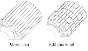
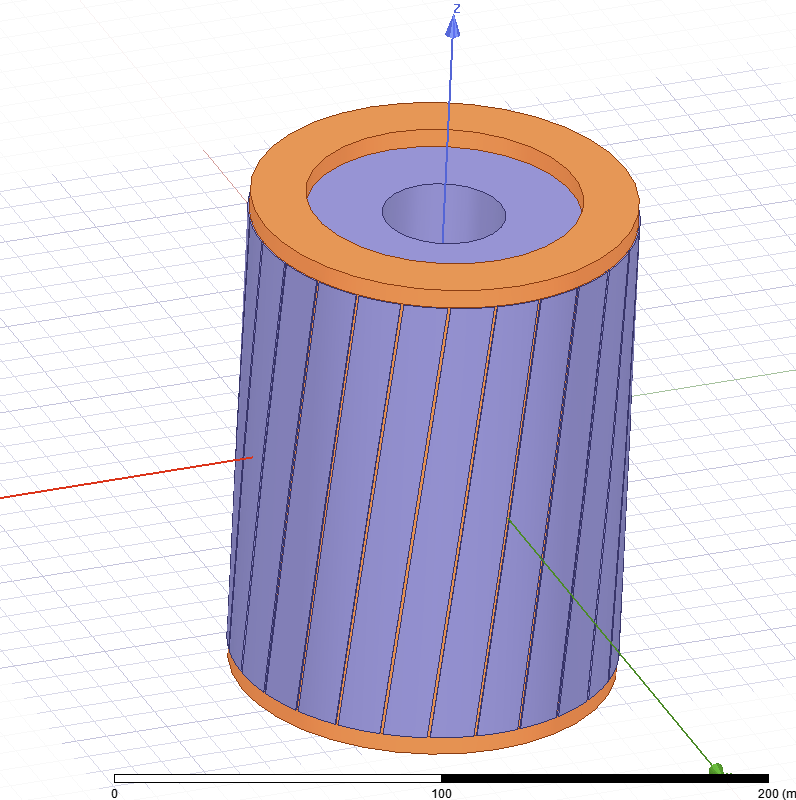
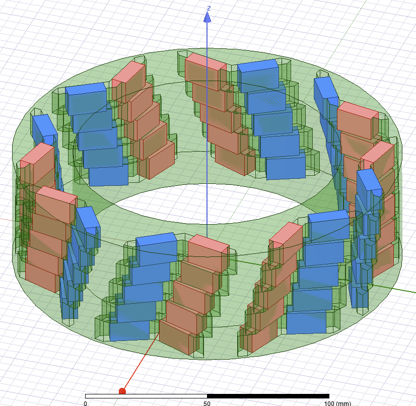
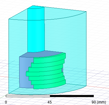
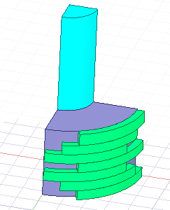
For Maxwell 2D transient designs with cylindrical rotational motion setup, the transient solver can take into account the effects of skewed rotor slots by using a multi-slice model.
To enable use of the multi-slice skew model:
- Right-click on Model in the Project Manager tree and select Set Skew Model on the context menu to open the Design Settings dialog to the Model Settings tab. You can also click Maxwell 2D > Design Settings to open the Design Settings dialog box, then select the Model Settings tab. You can also view and set design settings by selecting the current design, and then in the Properties window, select the tab for the solver.
- Check the Use Skew Model check box to enable the parameter fields below it.
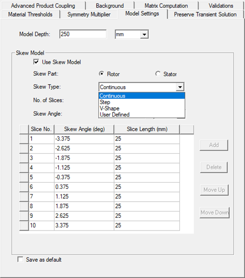
- Select either Rotor or Stator as the Skew Part being modeled. Default is Rotor.
- Select a Skew Type.
- Continuous (the default) - usually used in induction machines
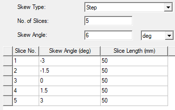
- Step - usually used in PM machines
- V-Shape
- User Defined
- Continuous (the default) - usually used in induction machines
- For Continuous, Step, and V-Shape skew types:
- Enter the No. of Slices that you want the model divided into in the Z-direction. The input must be a positive integer value greater than zero. The default is 5. You can also enter a variable name. (No. of Slices is not used for the User Defined skew type and is grayed out .)
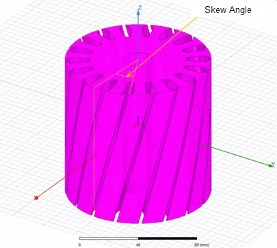
- Enter the Skew Angle and unit of measure of the part. The Skew Angle is the angle between first and last slice (not between two adjacent slices). Entries are non-negative real numbers in the range of 0 to 180 degrees inclusive (or equivalent values in units of measure such as radians). The default value is 5 degrees. You can also enter a variable name.
The Skew Angle and Slice Length values for each slice are calculated by the modeler and are listed in the (non-editable) table.
- For the User Defined skew type:
- Select a Skew Angle Unit, which will be applied to the Skew Angle values you enter in the table.
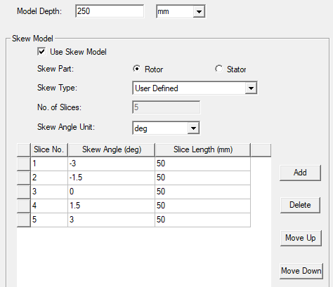
- Enter the desired Skew Angle and Slice Length values for the selected skew part. If the total of the Slice Length values differs from the Model Depth value, a message informing you of the difference will display in the Message Manager. Add, Delete, Move Up, and Move Down buttons allow you to control the table row entries.
- Select a Skew Angle Unit, which will be applied to the Skew Angle values you enter in the table.
- When finished, click OK to close the window.