
Harmonic Force Calculation in Maxwell 2D with Skew Model
Maxwell 2D supports object-based harmonic force calculation using a multi-slice skew model along the axial direction of rotating machines. (Element-based harmonic force calculation is not applicable to 2D multi-slice skew model.)The multi-slice skew model can improve the accuracy of Maxwell 2D simulation when the slot/teeth on the stator/rotor are skewed. By using a skew model, 2D vibration modeling in Ansys Mechanical is no longer valid; thus, 3D simulation must be performed instead by applying object-based harmonic force calculation slice-by-slice.
Skew Model Setup
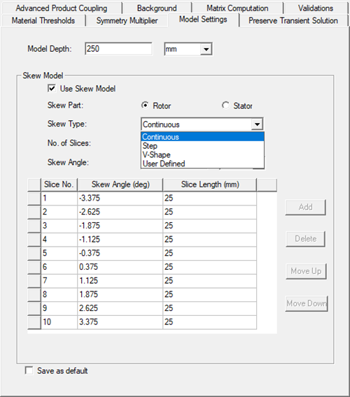
Skew model setup in Maxwell 2D is defined on the Model Settings tab of the 2D Design Settings dialog as described in the Model Settings Tab topic.
To create 3D geometry, the center position of each slice must be set properly:
-
Create a 2D full model in Maxwell (do not unite half teeth at the M-S boundary), and generate 3D geometry of one slice; then create a Maxwell 3D design, and duplicate one slice in the Maxwell 3D.
-
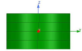
Move the center of the 3D geometry to the origin of the global coordinate system; then set the Z axis as the rotating axis.
-
Rotate each slice to its individual circumferential position: slice angle is taken from the skew model settings (see figure above). The slice number indices are arranged from least to greatest, corresponding to Z coordinates of slice position (from least to greatest).
For object-based harmonic force calculation, only one group of harmonic force components is generated for each selected object when skew model in not enabled in Maxwell 2D transient solver; and the Z coordinate of the object is set to zero by default. The “zero” Z position is used to match the selected geometry in Mechanical if coupled with the Harmonic response 3D solver.
|
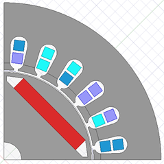
Maxwell 2D Partial Model |
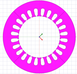
2D full model (stator only) |
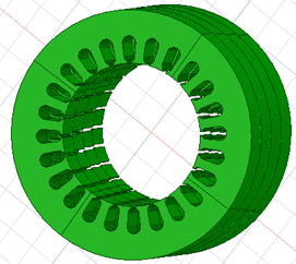
3D geometry of stator (one slice) |
|
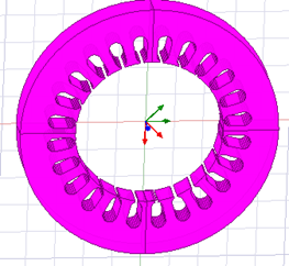
3D geometry after moving and rotating |
3D geometry in harmonic response solver |
Harmonic Force Calculation Requirements for Maxwell 2D Slice Model
Because the harmonic force calculated from the 2D slice model will be applied to a 3D model in Ansys Mechanical, it is very important to have a rule to link the skew angle to the slice number, and the slice number to the z-position in the Maxwell 2D solver. The relationship between slice number and z-position will determine how the 3D model will be generated.
The general rule is as follows:
- The sequence of slice number: from least to greatest with z position (this is for customer, not in the solver)
- The z-position: from least to greatest
- The skew angle: one-to-one with slice number, from slice 1 to slice N
The user generates 3D model based on skew angle, slice by slice, from least z-position to greatest z-position.