
ECET Model
The ECET model is used to set up the sweeping of the magnetizing current for each phase of a single- or poly-phase transformer. To change the name of the model placed on the sheet, click the symbol on the sheet, and change the name of the component in the property window (Value field in the DeviceName line, with the Parameter Values tab selected).

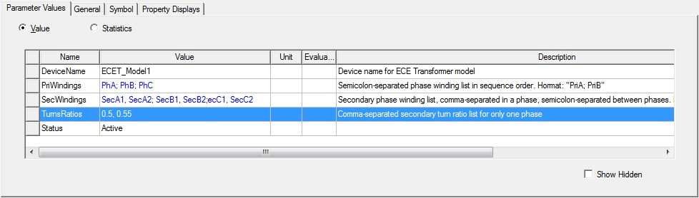
ECET_Model1
The ECET_Model contains the following parameters:
- DeviceName − the name of the device model with the default name as ECET_Model1;
- PriWindings − the name list of all primary windings with semicolons for separators between phase;
- SecWindings − the name list of all secondary windings with semicolons for separators between phases;
- TurnsRatios − the ratio of the secondary turns to the primary turns for only one phase.
If a transformer has two or more secondary windings for one phase, the secondary winding name list is separated by commas between winding names for the same phase, and TurnsRatios is a value list, instead of a single value, which is separated by commas between values for one phase. For example, for a three-phase transformer with two secondary windings for each phase, the parameters for ECET_Model are set as:
An ECET_Model cannot be used individually. It should be used combined with an ECEW_Model and/or an ECE3_Model.
In an ECE model look-up table, only the magnetizing inductance for each phase is assumed to be nonlinear, and all leakage inductances for all primary and secondary windings are assumed to be constant. Therefore, only the magnetizing current of the primary winding for each phase is required to be swept, which reduces the number of sweeping points significantly.
For ECE model creation, the setup of Stop Time and Time step are ignored. At Maxwell run time, the circuit simulator assigns currents for all windings step-by-step based on the list of current sweeps until all sweeps are finished. An ECE model is created automatically.
You can import this ECE model in Twin Builder via the Twin Builder > SubCircuit > Maxwell Component > Add Equivalent Circuit menu command. When the ECET_model is created and then imported into Twin Builder the following additional parameters are made available for use in Twin Builder:
-
r1_[WindingName] is winding resistance (default = 0)
-
l1_[WindingName] is end leakage inductance (default = 1mOhm, for 3D always = 0)
-
i0_[WindingName] is initial current (default = 0)
For more information on coupling Maxwell equivalent circuit designs to Twin Builder components, refer to the Maxwell Equivalent Circuit Component topic in the Twin Builder Help.
For more information on coupling Maxwell designs to Twin Builder components, refer to Coupling Maxwell to a Twin Builder Component.