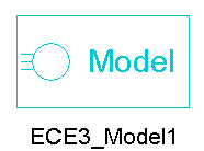
ECE3 Model
The ECE3 model enables you to create an ECE model from Maxwell Transient solutions. Compared with the procedure for creating ECE model from Maxwell Magnetostatic solutions, creating an ECE model directly from Maxwell Transient solutions takes advantage of winding and motion setups in Maxwell Transient.
The ECE3 model is used to set up the sweeping of currents in three-phase windings. To change the name of the model placed on the sheet, click the symbol on the sheet, and change the name of the component in the property window (Value field in the DeviceName line, with the Parameter Values tab selected).

The ECE3_Model contains the following parameters:
- DeviceName – the name of the device model with default name ECE3_Model1.
- Windings – specifies the comma-separated name list of three-phase windings whose currents are to be swept.
- CurrentSweeps – Specifies the current amplitude sweep list. For this, individual comma-separated values or range of values (linear step) can be specified.
- For individual current values, the syntax is “v1, v2, v3” (e.g., 0 A, 5 A, 10 A). The values must be input in ascending order (i.e., v1<v2<v3,…)
- For a value range with linear step, the syntax is (dv1, n1), where dv1 denotes the step and n1 the number of steps.
- Value ranges always require an initial value, which is set to 0A by default.
- For example, "(0.5 A, 5)" is equivalent to "0, 0.5 A, 1 A, 1.5 A, 2 A, 2.5 A"
- Multiple value range inputs can be combined with each other. The later value range input will start with its first linear step at the end of the preceding value range.
- For example, "(0.5 A, 5), (1 A,2)" is equivalent to "0, 0.5 A, 1 A, 1.5 A, 2 A, 2.5 A, 3.5 A, 4.5 A"
- (Multiple) value range inputs can also be combined with individual values. Value range inputs always start from the last current step defined.
- For example, "(0.5 A, 5), 3 A, (1 A, 2)" is equivalent to "0, 0.5 A, 1 A, 1.5 A, 2 A, 2.5 A, 3 A, 4 A, 5 A"
- Make sure that the individual value inputs are larger than the last current value of value ranges preceding it. (e.g., 3 A > 2.5 A=5*0.5 A as in the example above.)
PhAngIntervals – specifies the sweep types, or the number of phase-angle sweep intervals. For three-phase windings, only two independent variables are swept to derive three-phase currents, instead of directly sweeping three-phase currents. The two independent variables could be DQ currents (Id, Iq), two-phase currents (Iα, Iβ), or current amplitude and phase angle (Im,β).
PhAngIntervals = 0, 1, or 2, is defined for the DQ current sweep type, and 3 for the two-phase current sweep type.
- When PhAngIntervals = 0, both Id and Iq are swept based on the original setup of CurrentSweeps, and the look-up table is extended according to odd-symmetric conditions in a post-processing step.
- When PhAngIntervals = 1, the Id sweep is extended symmetrically to sample negative and positive current values. In contrast, the Iq sweep is based on the original setup of CurrentSweeps and extended in the look-up table according to odd-symmetric conditions in a post-processing step.
- When PhAngIntervals = 2, both Id and Iq sweeps are extended symmetrically from negative to positive, sampling positive and negative values for both, Id and Iq. Accordingly, the computed look-up table does not need to be extended in post-processing.
- When PhAngIntervals = 3, both Iα and Iβ sweeps are extended symmetrically from negative to positive, and the computed look-up table is not extended in post-processing.
- When PhAngIntervals ≥ 12, the current amplitude and phase angle sweep type are defined. The current amplitude Im is swept based on the setup of CurrentSweeps, and the phase angle is swept from 0 to 360 electrical degrees with the increment Δβ = 360°/(PhAngIntervals).
An ECE3_Model can be used individually to create the ECE model of a three-phase inductor, or combined with the ECER_Model for three-phase PM machines. It can also be combined with the ECER_Model and ECEW_Model for winding excited three-phase synchronous machines. An ECE3_Model with DQ current sweep type must always be used with an ECER_Model.
For ECE model creation, the setup of Stop Time and Timestep are ignored. At Maxwell run time, the circuit simulator assigns currents for all windings step-by-step based on the lists of current sweeps until all sweeps are finished. An ECE model is then created automatically. You can import this ECE model in Twin Builder via the Twin Builder > SubCircuit > Maxwell Component > Add Equivalent Circuit menu command. For more information on coupling Maxwell designs to Twin Builder components, refer to the Maxwell Equivalent Circuit Component topic in the Twin Builder Help.
For more information on coupling Maxwell designs to Twin Builder components, refer to the Coupling Maxwell to a Twin Builder Component topic in the Maxwell Help.
