
ECE6 Model
The ECE6 model enables you to create an ECE model from Maxwell Transient solutions. Compared with the procedure for creating ECE model from Maxwell Magnetostatic solutions, creating an ECE model directly from Maxwell Transient solutions takes advantage of winding and motion setups in Maxwell Transient.
The ECE6 model is used to set up the sweeping of currents in a six-phase winding, which is described as dual three-phase windings. These two three-phase windings are shifted by 30 electrical degrees. The figure below shows the set-2 three-phase windings lagging behind the set-1 three-phase windings by 30 electrical degrees, and dq axes in rotor with the q-axis lagging behind the d-axis by 90 electrical degrees.
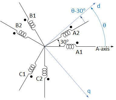
If the rotor initial position is defined with θ = 0 as the position where the rotor d-axis aligns with the axis of the phase A1 winding. That is, the phase A1 gets maximum flux linkage when θ = 0.
To change the name of the model placed on the sheet, click the symbol on the sheet, and change the name of the component in the property window (Value field in the DeviceName line, with the Parameter Values tab selected).
The ECE6_Model contains the following parameters:
- DeviceName – the name of the device model with default name ECE6_Model1.
- Windings – specify winding names in the order of arrangement. Windings are separated by commas within each three-phase set, and by semicolon between the two three-phase sets. Notice that the winding list always starts with the leading set and ends with the lagging set. For the phase windings as shown in the figure above, the winding list is specified as:A1 B1, C1; A2, B2, C2
- CurrentSweeps – to specify sweeping values for d- and q-axis currents, Id and Iq, respectively, you only need to list 0 and all positive sweeping currents. All negative currents will be swept, or extended, symmetrically from the specified positive sweeping values. For example: 0, 1, 10.
- PhAngIntervals – specify the type to extend the sweeping list and look-up table. Valid values are: 0, 1, or 2 only. Value 0 specifies the type that both Id and Iq are post-extended; Value 1 specifies the type that Id is pre-extended, and Iq is post-extended; Value 2 specifies the type that both Id and Iq are pre-extended. Here, “pre-extended” means the sweeping list for a current is symmetrically extended from the sweeping values specified in CurrentSweeps, and “post-extended” means the look-up table for a current, which is derived from the sweeping values specified in CurrentSweeps, is extended based on even or odd symmetric conditions. In a post extension, the symmetric conditions are applicable only for fundamental fields. Therefore, it is not necessary to consider all harmonics in the look-up table for post-extended variables. In such a case, all harmonic components will be filtered by using the average values over various rotor positions for all dq0 flux linkages and torque to reduce the length of the look-up table.
- Res – phase winding resistance (available when Show Hidden is checked).
- IndE – phase end-leakage inductance (available when Show Hidden is checked).
Transformation between the Six-Phase and dq0 Systems
The current transformation from dq0 system to set-1 ABC system is

where

Because the set-2 winding lags behind the set-1 winding by 30 electrical degrees, the current transformation from dq0 system to set-2 ABC system is

The contribution of 0-axis currents (I01, I02) to winding flux linkages can be considered by zero-inductance L0, which is usually assumed to be constant. Therefore, it is not necessary to sweep 0-axis currents. In general, to cover all possible operation cases, the remaining four independent currents (Id1, Iq1, Id2, Iq2) need to be swept. However, in most applications, to get the benefits of 6-phase windings, these dual three-phase windings are operated with balanced currents, that is, in the winding set lagging behind by 30 electrical degrees in space, the currents lag behind by 30 degrees in time. In such cases, the dq currents on both winding sets are the same. Therefore, to save FEA simulation time, sweep only two independent currents (Id, Iq) during FEA simulation, and assign

During circuit simulation, measure dual three-phase currents (IA1, IB1, IC1) and (IA2, IB2, IC2), and transform them to dq currents by

and

where

The dq currents used in the look-up table are:

Because the two sets of three-phase windings have the same turns, the fundamental field produced by the average dq currents will be the same as that produced by the real dq currents. Therefore, for unbalanced operations, replacing the real dq currents (Id1, Iq1) and (Id2, Iq2) in the two winding sets by the average dq currents (Id, Iq) will not cause noticeable errors.
Circuit Model and Look-up Table
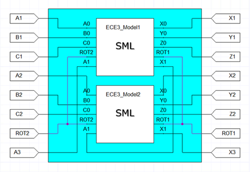
The circuit model for 6-phase machines consists of two sub-circuits of 3-phase machines with the dq currents of the other sub-circuit being the input arguments, as shown below, where the initial position, an input argument of the sub-circuit model, of ECE3_Model2 is set 30 electrical degrees lagging behind ECE3_Model1. The mechanical ports represented by (ROT1, ROT2) of the two sub-circuit are connected in parallel, and the torque values in the look-up table are a half of the FEA solutions for each sweep. The field winding, if it exists, represented by (A3, X3) in the circuit model, is obtained by series connection of the field windings, represented by (A1, X1), of the two sub-circuits.
The flux linkage values in the look-up table of the field winding in the sub-circuit are a half of the FEA solutions. The input dq currents of the other subcircuit are used to get the average dq currents as the input of the look-up table. The following is an example of the data structure of the look-up table of a 6-phase machine with wound field.
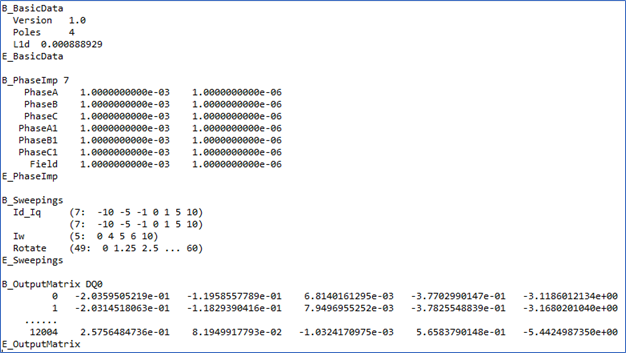
The subcircuit data include basic data, specified resistances and leakage inductances of all windings, value list for all controlling variables, and value list for all controlled variables of all sweeps.
The basic data are listed between “B_BasicData” and “E_BasicData”, which include the version number, the number of poles, and d- and q-axis leakage inductance between the 2-set 3-phase windings.
The data between “B_PhaseImp” and “E_PhaseImp” list the winding resistances and end leakage inductances, which are not included in 2D FEA results, for each winding. The winding resistances and end leakage inductances are obtained from specified parameters Res and IndE of the ECE6_Model, as well as ECEW_Model if it is included.
The data between “B_Sweeping” and “E_Sweeping” provide all sweeping variables, and their sweeping data lists. Each sweeping variable, corresponding to one ECE sweeping model, starts with a keyword and follows one or two sweeping data list. The sweeping data list is in the format of (n: v0 v1 … ) representing the number of sweeps and sweeping values. Keyword “Id_Iq” means the dq current sweep, “Iw” represents wound field current sweep, and “Rotate” indicates the rotor position sweep.
The data between “B_OutputMaxtrix” and “E_OutputMatrix” lists solutions of all sweeps. The first column is the sweeping index from 0 to n-1, here n is the total number of sweeps. The total number of sweeps is 7x7x5x49 = 12005. The 2nd to 4th columns list the dq0 flux linkages of all sweeps for the present sub-circuit. If the field winding exists, the 5th column lists its flux linkage. The last column list torque values of all sweeps.
From FEA solutions, we get results of flux linkages of all windings. The dq0 flux linkages can be obtained from

and

Because set-2 windings lag behind set-1 windings by 30 electrical degrees, the ABC flux linkages of the set-2 windings will lag behind those of the set-1 windings by 30 degrees. As the result, the dq0 flux linkages satisfy

The repeatable period for the d- and q-axis flux linkages is 60 electrical degrees, but that for the 0-axis flux linkage is 120 electrical degrees. Therefore, all dq0 flux linkages must be extended to 120 electrical degrees by

The extended dq0 flux linkages in the final look-up table are based on the same dq currents in two winding sets. During the circuit simulation, if the dq currents in the two windings are not the same, the dq flux linkages obtained from the look-up table must be modified as described below. The modified d-axis flux linkage is


where lFd is the flux linkage produced by wound field winding current, or PM, and


which can be directly obtained from the look-up table. Similarly, the q-axis flux linkage is modified by

where L1q = L1d, and lq1 can be directly obtained from the look-up table. To filter the slot effects, the d- or q-axis leakage inductance L1d can be computed from

where i represents the sweeping index.
The d- and q-axis self-inductance and mutual inductance between 2 winding sets are derived from

and

For ECE model creation, the setup of Stop Time and Timestep are ignored. At Maxwell run time, the circuit simulator assigns currents for all windings step-by-step based on the lists of current sweeps until all sweeps are finished. An ECE model is then created automatically. You can import this ECE model in Twin Builder via the Twin Builder > SubCircuit > Maxwell Component > Add Equivalent Circuit menu. For more information on coupling Maxwell designs to Twin Builder components, refer to the Maxwell Equivalent Circuit Component topic in the Twin Builder Help.
For more information on coupling Maxwell designs to Twin Builder components, refer to the Coupling Maxwell to a Twin Builder Component topic in the Maxwell Help.