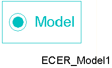
ECER Model
The ECER model enables you to create an ECE model from Maxwell Transient solutions. Compared with the procedure for creating ECE model from Maxwell Magnetostatic solutions, creating an ECE model directly from Maxwell Transient solutions takes advantage of winding and motion setups in Maxwell Transient.
The ECER model is used to set up the sweeping of rotor position. To change the name of the model placed on the sheet, click the symbol on the sheet, and change the name of the component in the property window (Value field in the DeviceName line, with the Parameter Values tab selected).

The ECER_Model contains the following parameters:
- DeviceName –the name of the device model with default name ECER_Model1.
- RotAngMax – specifies the maximum rotating angle (in mechanical degrees) for sweeping.
- InElecDeg – check to define RotAngMax in electrical. degrees, uncheck to define in mechanical degrees
- RotAngIntervals – specifies the number of uniform sweep intervals for rotating angle.
- SkewAng – specifies the skew angle (in mechanical degrees) of the stator or rotor core for 2D only.
- Poles – specifies the number of poles of the machine.
- Slots – specifies the number of stator slots to determine cogging torque period (available when Show Hidden is checked).
- Output – specifies how the look-up table outputs the winding flux linkages. 0 for flux linkages in ABC; 1 for flux linkages in DQ0; 2 for inductances in DQ and field flux linkage (available when Show Hidden is checked).
An ECER_Model cannot be used individually. It should be used combined with an ECEW_Model and/or an ECE3_Model for rotational electrical machines. When DQFluxOutput is checked, it must be combined with an ECE3_Model.
For ECE model creation, the setup of Stop Time and Timestep are ignored. At Maxwell run time, the circuit simulator assigns currents for all windings step-by-step based on the lists of current sweeps until all sweeps are finished. An ECE model is created automatically. You can import this ECE model in Twin Builder via the Twin Builder > SubCircuit > Maxwell Component > Add Equivalent Circuit menu command. For more information on coupling Maxwell designs to Twin Builder components, refer to the Maxwell Equivalent Circuit Component topic in the Twin Builder Help.
For more information on coupling Maxwell designs to Twin Builder
components, refer to Coupling Maxwell to a Twin Builder Component.
