
Drawing a Helix
A helix is a 3D spiral object created by sweeping a line or 2D sheet object along a vector that you define. The center of the helix is the defined by the placement of the vector relative to the swept object. You must define the vector so that the swept object will not self-intersect, the rule being, do not draw the vector so that it centers on or overlaps a selected 2D object. After you create the vector, the Helix dialog box opens, where you then specify the turn direction, pitch, number of turns, and radius of the turn to define the helix.
Sweeping a 2D object results in a hollow 3D object. Sweeping a 2D sheet object results in a 3D solid object.
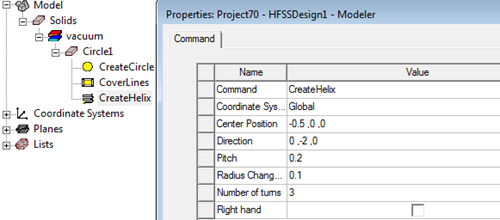
Once you have created a helix, you can changing it by edit the properties of the original object, and by editing the helix command properties for coordinate system, center position (which corresponds to the vector placement), direction, pitch, turns, radius change, and direction.
To create a helix:
- Create and select the line or 2D object you want to
sweep to form a helix.
Selecting a valid object enables the Helix icon on the Draw tab of the ribbon.
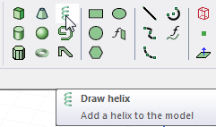
- Click Draw > Helix or in the Draw tab of the ribbon, click the helix icon:
- Draw the vector you want to sweep the object around. The two points that describe the vector affect axis location and direction only and not the helix length. (The vector definition corresponds to the Center Position and Direction properties in the CreateHelix command in the History tree.) The helix length is determined when you enter the pitch and number of turns in the Pitch and Turns text boxes. The initial radius of the helix is determined by the axis position relative to the object being swept. It is important that the swept object cannot intersect itself. For a 2D object, you should ensure that the vector you draw does not intersect the interior. If it does, the object cannot be drawn due to self-intersection and you receive a message that "Body could not be created because of invalid parameters."
- Select the start point by clicking the point or typing its coordinates in the X, Y, and Z text boxes. (Remember that you can also edit the parameters of a completed helix).
- Select the endpoint by clicking the point or typing its coordinates relative to the start point in the dX, dY, and dZ boxes.
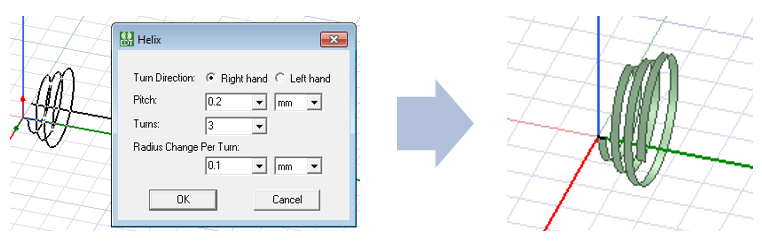
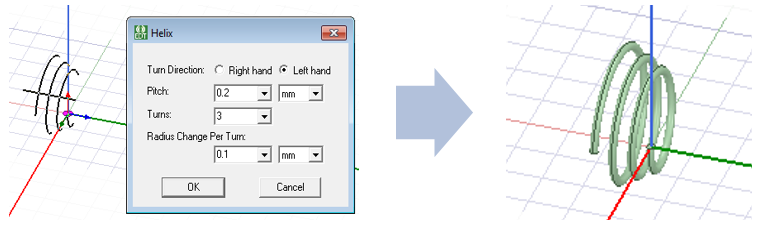
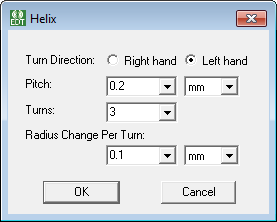
- For Turn Direction, select Right hand if the turn direction is clockwise and Left hand if the turn direction is counter-clockwise.
- In the Pitch text box, type the distance between each turn in the helix, and click a unit in the drop-down menu.
- In the Turns text box, type the number of complete revolutions the object will make along the vector.
- In the Radius Change per Turn text box, type a number for the increase in the radius and select the units from the drop-down menu.
- After you set these values, the selected object is swept along the vector to form a helix. The original object you swept is deleted.
- Click OK to create the Helix. If the Modeler option for editing properties of new primitives is checked, the Properties dialog box appears, enabling you to modify the object's properties. You can also select the commands for the object and the helix command in the History tree to access and edit their properties.
The Helix dialog box appears.
For details about these commands, see Technical Notes, Surface Approximations and related sections, Modifying Surface Approximations, and Guidelines for Modifying Surface Approximations.
Related Topics
Drawing a Segmented Helix with Polygon Cross-Section using a User-Defined Primitive
Drawing a Segmented Helix with Rectangular Cross-Section using a User-Defined Primitive