
Drawing a Segmented Helix with Rectangular Cross-Section Using a User-Defined Primitive
Ansys provides you with a DLL to define the parameters of a segmented helix with a rectangular cross-section.
- Click Draw > User Defined Primitive > SegmentedHelix > RectHelix.
- Specify the values for the following parameters:
RectHeight
Height of rectangular cross-section.
RectWidth
Width of rectangular cross-section.
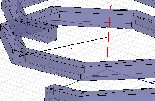
StartHelixRadius
The radius of a segmented helix is defined from the helix center of rotation to the center of the helix cross-section at segment transitions. The first and last segments of the helix are half segments. See this figure.
RadiusChange
The radius change per turn of the helix.
Pitch
Distance between helix turns.
Turns
The number of turns in the helix.
SegmentsPerTurn
The number of segments constructing each turn. Enter zero (0) for true curve.
RightHanded
Helix winding direction. Enter non-zero value for right-handed helix.
- Click OK.
The Create User Defined Part window appears. The Parameters tab permits you to edit the parameters. An Info tab contains information about the user-defined primitive, its purpose, the company/author who created it, the date created and the version number.
Related Topics
Creating a User-Defined Primitive
Drawing a Segmented Helix with Polygon Cross-Section using a User-Defined Primitive