
Defining an Inner-Rotor Induction Machine
The general procedure for defining an Inner-Rotor Induction Machine is as follows:
-
Insert an Inner-Rotor Induction Machine into a new or existing project by choosing Generate RMxprt Solutions for the Design Flow, General for the Machine Type, then select Inner-Rotor Induction Machine from the expandable list.
-
Click the Machine entry in the project tree to set the machine properties as shown:
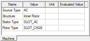
- Click to expand the Machine > Stator entry in the project tree to define data for the stator and its associated core and core slot, winding, and optionally, vent for the SLOT_AC core type.
- Click to expand the Machine > Rotor entry in the project tree to define data for the rotor and its associated core, damper and damper slot, and optionally, vent for the SLOT_CAGE core type.
-
Click the Machine > Shaft entry in the project tree to define the magnetism, frictional and windage losses, and reference speed of the shaft.
-
Optionally, right-click the Machine entry in the project tree and click Insert Housing to add a machine housing.
-
Right-click Analysis in the project tree, and click Add Solution Setup to define the solution data.
- Choose File > Save to save the project.
- Choose RMxprt > Analyze to analyze the design.
Once analyzed, the model can be used to create a new Maxwell 2D or 3D design.
Related Topics
Analysis Approach for Three-Phase Induction Motors
Defining Data for the SLOT_AC Core Type
Defining Data for the SLOT_CAGE Core Type
Defining the Shaft Data for a Generic Rotating Machine
Setting Up Analysis Parameters for a Generic Rotating Machine