
Analysis Approach for Three-Phase Induction Motors
For a three-phase induction motor, the stator winding (with a sinusoidal spatial distribution and p pairs of poles) is connected to a three-phase symmetric voltage power supply. The resulting currents in the stator produce a rotating magnetic field. The rotor winding is often a squirrel cage type with the number of poles dictated by the number of poles in the stator. Currents are induced in the rotor bars and produce, in turn, a second rotating magnetic field. The two rotating fields produce a resultant rotating magnetic field in the air gap of the machine. The interaction of this field in the air gap with the rotor bar currents produces an electromagnetic torque, which acts on the rotor in the direction of the rotation of the field in the air gap. A torque of equal value acts upon the stator in the opposite direction.
The stator winding, which is connected to a phase of the supply system, has p coils, each with a symmetric spatial distribution and an opening of pD/2p, where D is the diameter of the winding. In this case, the magnetic field in the air gap has p periods, and the winding has p pairs of poles.
The performance of three-phase induction motors (IndM3) is analyzed based on the equivalent circuit of one phase in the frequency domain as shown in Figure 1.
In the figure, R1 is the stator resistance, X1 is stator leakage reactance, which consists of stator slot leakage reactance, end-winding leakage reactance, and differential leakage reactance. X2 and R2 are rotor leakage reactance and rotor resistance, respectively. X2 includes rotor slot leakage reactance, end-ring leakage reactance, differential leakage reactance, and skewing leakage reactance. Due to the saturation of the leakage field, X1 and X2 are nonlinear. The parameters in the equivalent circuit are dependent on the stator and rotor currents. Due to the skin effects, X2 and R2 are the equivalent values from a distributed-parameter circuit, as shown in Figure 2.
They vary with the rotor slip s. All rotor parameters have been referred to the stator side.
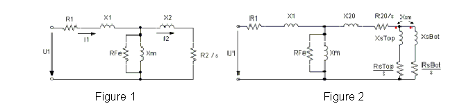
In the exciting branch, Xm is the magnetizing reactance, and RFe is the resistance corresponding to iron-core losses. Xm is a linearized nonlinear parameter that varies with the saturation of the main field.
After a phase voltage U1 is applied to the phase terminals, stator phase current I1 and rotor current I2, which has been referred to the stator, can be easily computed by the circuit analysis. The electromagnetic power Pm, or air-gap power, is computed by the following:
Pm = 3 * I2^2 * R2/s
The electromagnetic torque Tm is
Tm = Pm/w
where w is the synchronous speed in rad/s.
The output mechanical shaft torque T2 is
T2 = Tm - Tfw
where Tfw is the frictional and wind torque.
The output power is:
P2 = T2 * w2
where w2 = w* (1 - s) and is rotor speed in rad/s.
The input power is:
P1 = P2 + Pfw + Pcu2 + PFe + Pcu1 + Ps
where Pfw, Pcu2, PFe, Pcu1, and Ps are frictional and wind loss, rotor copper loss, iron-core loss, stator copper loss, and stray loss, respectively.
The power factor is derived from
PF = P1/(m * U1 * I1)
The efficiency is computed by
eff = P2/P1 * 100%