
Coupling Maxwell Designs with Ansys Structural via Workbench
Stress feedback coupling between Maxwell 2D/3D and Ansys Structural is supported via the Workbench schematic. Stress feedback is supported for Maxwell magnetostatic, eddy current, and transient types. Users also need to set up the design and geometry appropriately. An appropriate design has one or more solve setups that are enabled for stress feedback. The process for stress feedback coupling between Maxwell and Ansys Structural is similar to that described in Coupling Maxwell Designs with Ansys Thermal via Workbench.
- The easiest way to add a Maxwell 2D or 3D design to a Workbench schematic is to import a working design via WorkbenchFile > Import. The imported design is placed in the Workbench schematic after it is successfully imported.
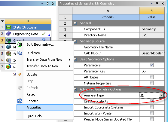
- Next, insert a Static
Structural system and change its Analysis
Type to 2D or 3D, (depending on the Maxwell design type)
by right-clicking on the Geometry
cell and selecting Properties. It
is important to change the Steady-State Thermal
system's analysis type before setting
up its geometry.
- To set up the Static Structural system's geometry, you must first export the Maxwell geometry using sat or step format as follows:
- Select the Modeler > Export menu item.
- Select the desired model geometry format (sat or step), and the save location in the dialog box and save the file for use by Ansys Workbench.
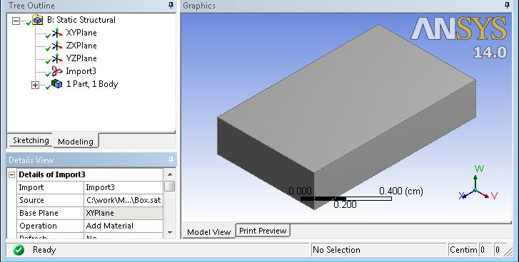
- Import the file via the Geometry module of the Static Structural system.
- To access the Geometry module, double-click on the Geometry cell in the Static Structural system to launch Design Modeler.
- Select File > Import External Geometry File and browse for the geometry file exported from Maxwell.
- After the geometry file is imported,
right-click on the root folder of the modeler project tree and select
Generate. (When the geometry
file is of a Maxwell 2D RZ design, users can rotate the geometry in Design Modeler by creating a body operation.)
- Close Design Modeler and refresh the Model cell of the Static Structural system by right-clicking the Model cell and selecting Refresh.
- The geometry mode of the Static Structural system can be changed via the Ansys Mechanical user interface.
- Launch Mechanical by double-clicking the Setup cell of the Static Structural system.
- Select Geometry in the project tree and the Definition of Geometry will be shown in the Detail window.
- Select either Flexible or Rigid as the value for the property 2D (or 3D) Stiffness Behavior.
- To set up the coupling, drag the Solution cell of the Maxwell system and
drop it on the Setup cell of the
Static Structural system.
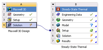
- Note that the Maxwell Solution cell is tagged with a “Lighting Bolt” symbol. Right-click on the Maxwell Solution cell and select Update. This will initiate a Maxwell simulation if it is not already solved. Once Maxwell's solution is available, the “Lighting Bolt” changes to a “Green Check” symbol.
- To “push” the coupling into Static Structural, right-click on the Static Structural Setup cell and select Refresh.
- After refresh is finished, you can launch Ansys Mechanical by double-clicking the Setup cell to finish the coupling setup, which is similar to that described in Coupling Maxwell Designs with Ansys Thermal via Workbench.
Related Topics
Coupling Maxwell with Both Ansys Thermal and Structural via Workbench