Context Area
The panel at the lower left of the window identifies the context to be used for the calculations. The top line identifies the design. Depending on the design, text entry boxes allow you to select a Solution, Field Type, Phase, or Time.
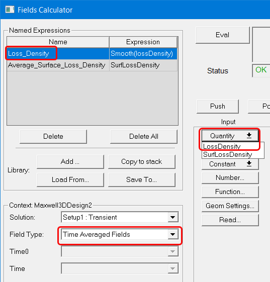
For Maxwell 2D and 3D transient solutions, the field type can be either Fields or Time Averaged Fields. Selecting Time Averaged Fields adds an additional Time0 field, which is used when calculating time averaged losses. Selecting Time Averaged Fields also adds Loss_Density as a Named Expression, and LossDensity as a Quantity command selection.
The Change Variable Values button opens a Set Variable Values dialog box. By default it has Use Nominal Design checked. Unchecking the box lets you select another variable value. OK the dialog to accept the selection.
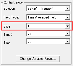
For Maxwell 2D transient solutions in which Use Skew Model is enabled on the Model Settings tab, an additional Slice field displays, which allows you to select the skew model slice to use for fields calculations.