
Calculating the Properties for Magnetostriction
The magnetostriction property supports four models: Linear, Nonlinear, Anisotropic, and Matrix. The property values you enter typically come from manufacturer data sheets.
To define these model properties, from the View/Edit Material dialog:
-
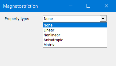
Click the Edit button to the right of Magnetostriction Custom to open the Magnetostriction properties dialog box:
-
Choose a Property type from the drop-down menu: Linear, Nonlinear, Anisotropic, or Matrix, and do one of the following:
-
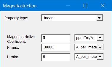
For Linear, enter values for Magnetostrictive Coefficient, H max, and H min.
-
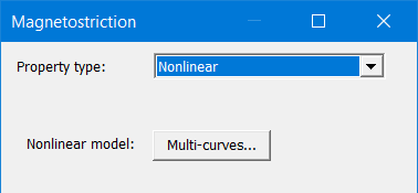
For Nonlinear, click the Multi-curves button to add one or more stress-dependent Lambda-H curves.
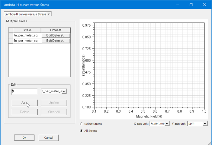
Enter a stress value in the Edit text box and click Add, then click Edit Dataset to open the Edit Dataset dialog box, in which you enter coordinate values for the Magnetic Field (H) and strain (Lambda).
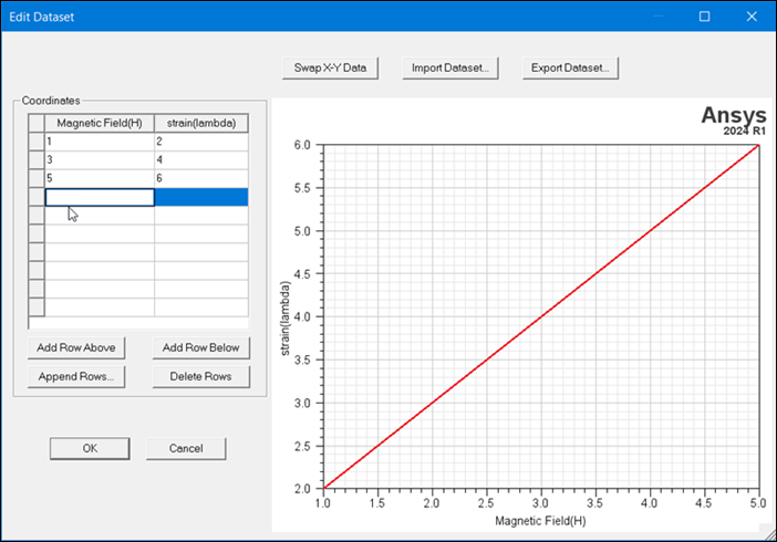
When finished, click OK to close the dialogs and return to the Magnetostriction dialog box.
-
For Anisotropic, select either Linear or Nonlinear from the Rolling Direction and Transverse Direction drop-down menus. Rolling Direction refers to the alignment of the crystalline structure (and associated magnetic domains) in the direction along which the material (such as the steel laminations used in transformers) passed through the rollers during manufacture. Transverse Direction is at right angle to the Rolling Direction. Magnetostriction property values typically differ in each direction.
Note: The type you select for each of the directions need not be the same. For example, you could select Linear for Rolling Direction and Nonlinear for the Transverse Direction, and vice versa.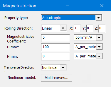
-
For Linear Rolling Direction only, enter the X, Y, and Z coordinate values. For Linear Transverse Direction, enter values for Magnetostrictive Coefficient, H max, and H min.
Note: The X, Y, and Z components of the Rolling Direction correspond to the Material Coordinate System Type set in the View/Edit Material window.- For Cartesian: X=X, Y=Y, Z=Z
- For Cylindrical: X=R, Y=Phi, Z=Z
- For Spherical: X=Rho, Y=Theta, Z=Phi
-
For Nonlinear, click the Multi-curves button to add one or more stress-dependent Lambda-H Curves.
Enter a stress value in the Edit text box and click Add, then click Edit Dataset to open the Edit Dataset dialog box, in which you enter coordinate values for the Magnetic Field (H) and strain (Lambda).
-
-
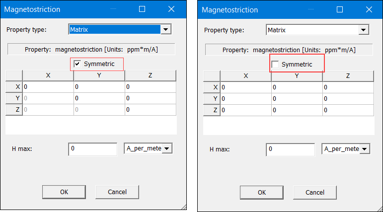
The Matrix type can be used to simulate magnetostrictive stress and deformation with full magnetostriction matrix [3x3]; with this type, a simulation can consider both isotropic and anisotropic magnetostriction effects. This property type is applicable to Maxwell 2D and 3D magnetostatic and transient designs.
The magnetostriction deformations and magnetic fields are linked via the following expression:

where λ is LambdaVector,
C is the CoefficientMatrix, and
H is HFieldVector.
H max (magnitude of H vector) setting seen below the matrix is also needed as saturation control.
-
-
When finished, click OK to close the dialog boxes and return to the Magnetostriction window.
- Click OK to close the Magnetostriction dialog box and return to the View/Edit Materials window.
If you want to use a variable to define any of the X, Y, and Z fields, the variable name must begin with $ because material properties only support project-level variables. For example, $a_value would be a valid name, but a_value would not.
Related Topics
Magnetostriction Modeling of Magnetic Material
Magnetostriction and Inverse Magnetostriction
Calculating the Properties for Inverse Magnetostriction