
Calculating the Properties for Inverse Magnetostriction
The inverse magnetostriction property supports three models: Linear, Nonlinear, and Anisotropic. The property values you enter typically come from manufacturer data sheets.
To define these model properties, from the View/Edit Material window:
-
Click the Edit button to the right of Inverse Magnetostriction Custom to open the Inverse Magnetostriction properties dialog box.
-
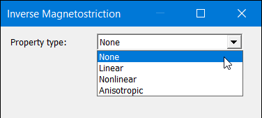
Choose a Property type from the drop-down menu: Linear, Nonlinear, or Anisotropic, and do one of the following:
-
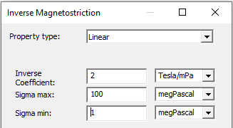
For Linear, enter values for Inverse Coefficient, Sigma max, and Sigma min, where sigma represents mechanical stress.
-
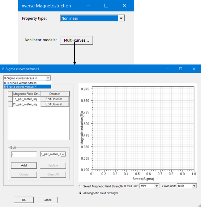
For Nonlinear, click the Multi-curves button to add one or more stress-dependent B-H curves, or H-dependent B-Sigma curves.
-
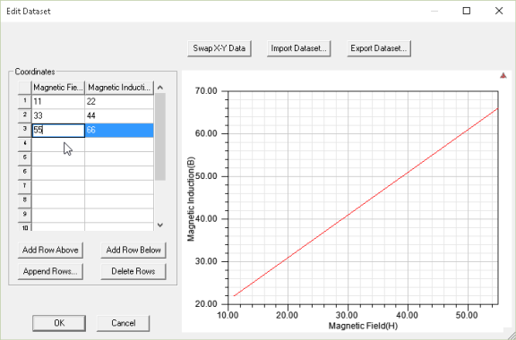
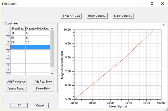
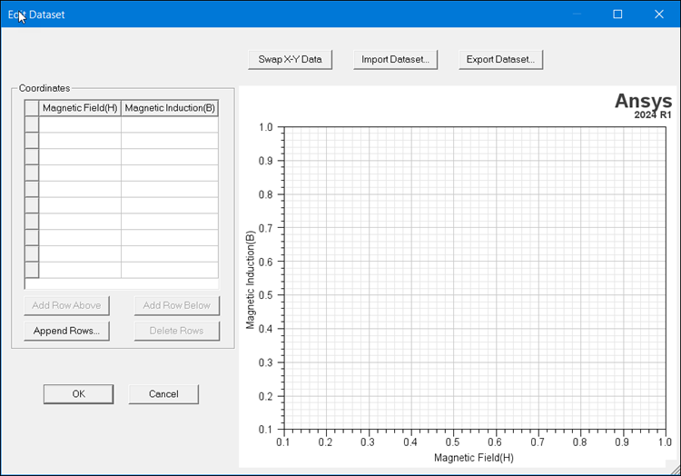
For B-H curves versus Stress (as shown above) – Enter a stress value in the Edit text box and click Add; then click Edit Dataset to open the Edit Dataset dialog box, in which you enter coordinate values for the Magnetic Field (H) and Magnetic Induction(B).
-
For B-Sigma curves versus H (as shown below) – Enter a magnetic field strength value in the Edit text box and click Add;
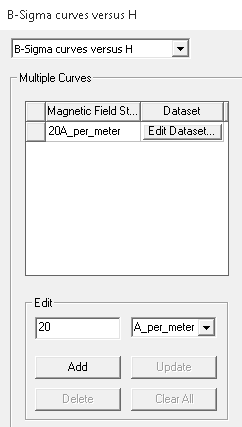
then click Edit Dataset to open the Edit Dataset dialog box, in which you enter coordinate values for the Stress (Sigma) and Magnetic Induction(B).
Note: Multiple B-H curves vs stress are interpolated, but not extrapolated. Therefore, B-H curves over the entire range of expected stress levels must be entered for positive stress (tensile stress pointing out of the object) and if anticipated negative stress (compressive stress pointing into the object).When finished, click OK to close the dialogs and return to the Inverse Magnetostriction dialog.
-
-
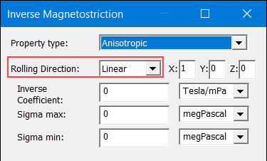
For Anisotropic, select either Linear or Nonlinear from the Rolling Direction drop-down menus. Rolling Direction refers to the alignment of the crystalline structure (and associated magnetic domains) in the direction along which the material (such as the steel laminations used in transformers) passed through the rollers during manufacture. Magnetostriction property values typically differ in each direction.
-
For LinearRolling Direction, enter the X, Y, and Z coordinate values, as well as Inverse Coefficient, Sigma max, and Sigma min, where sigma represents mechanical stress.
 Note: The X, Y, and Z components of the Rolling Direction correspond to the Material Coordinate System Type set in the View/Edit Material window.
- For Cartesian: X=X, Y=Y, Z=Z
- For Cylindrical: X=R, Y=Phi, Z=Z
- For Spherical: X=Rho, Y=Theta, Z=Phi
-
For Nonlinear, click the Multi-curves button to add one or more stress-dependent Lambda-H Curves or H-dependent B-Sigma curves.
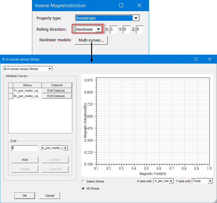
For example, for B-H curves vs Stress, enter a stress value in the Edit text box and click Add, then click Edit Dataset to open the Edit Dataset dialog box, in which you enter coordinate values for the Magnetic Field (H) and Magnetic Induction (B).
-
-
- Click OK to close the dialog and return to the View/Edit Materials window.
Related Topics
Magnetostriction Modeling of Magnetic Material