
Creating or Editing Package Definitions for Components
ODB++ and IPC2581 imports may include properties in their IDF files that describe the component outline or height properties of a component, while IDF imports may bring in thermal properties of a component. These properties describe the component's materials, thermal, power, outline, and heat sink characteristics. These properties can also be added to new components and are accessible through the Footprint tab of the Properties window.

Package definitions are only used for Icepak thermal analysis with linked PCB components, and when Mechanical projects import an Electronics Database (EDB) directly. It is not used by the electromagnetic solvers.
Complete these steps to add, create, or edit a new or existing package to a component.
- From the Components window, click a component.
- From the Footprint tab of the Properties window, click in the Value cell of the Package Definition row and select Edit to open the Package Definition Editor. It lists all packages available in the design.
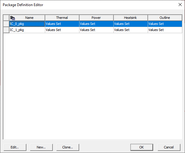
- To add an existing package, select the package on the list and click OK.
- To create a new package, click New.
- To edit an existing package, select the package on the list and click Edit to open the Package Definition window.
- Adjust the properties as chosen.
- Click OK.
- In the Package Definition Editor, select the package on the list and click OK.
- To view the package outline, enable Display package graphics in the Layout Options.
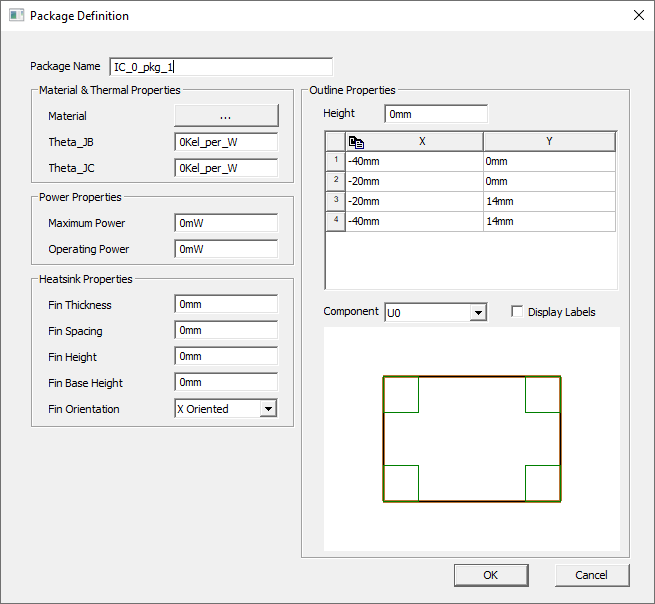
Packages contain four types of properties: materials and thermal, power, heat sink, and outline. The Materials & Thermal Properties are the materials the heat sink is made of and measured properties that describe the rate of its heat transfer from a junction to another location. Specifically they are:
- Materials: Allows you to select materials.
- Theta_JB: thermal resistance from junction to board. Include the unit Kel_per_W (Kelvin per Watt.)
- Theta_JC: thermal resistance between the junction and a point on the outside surface of the package (i.e., the case). (See the IDF specification 3.0 for details.) Include the unit Kel_per_W (Kelvin per Watt.)
The Power Properties are:
- Maximum Power: the greatest amount of power the package can handle.
- Operating Power: the average amount of power experienced during a typical load.
The Heatsink Properties simulate a three-dimensional modeling component that can exchange radiation with other objects in the model. The package defines an extruded heatsink which consists of a base and fins that run parallel to each other across the base.
HFSS 3D Layout produces as many fins as fit given the settings of these properties:
- Fin Thickness: how wide each fin is.
- Fin Spacing: how far apart each fin should be from its nearest neighbor.
- Fin Height: how tall each fin is.
- Fin Base Height: how tall the base on which the fins sit is.
- Fin Orientation: whether the fins are oriented along the X or Y axis.
The Outline Properties are a 3D representation of the component. The table lists the X and Y coordinates for the corners of the component and the Height is the elevation of the component box along the Z axis. Specify which component is represented in the Component drop down list. Click Display Labels to label the pins and vias on the diagram.