
Adding Skin-Depth Mesh Seeding to an HFSS 3D Layout Design
When the mesh is generated, the specified refinement criteria is used. This operation are approximately the same as having slabs of tetrahedra, but it is not guaranteed to prevent tetrahedra from crossing slab interfaces. Use caution with this mesh operation, as very thin layers may cause a reduction in mesh quality or unnecessarily cause the generation of a very large mesh. Also be careful because further regions refined under this operation and its close neighbors do not participate in solution adaptive refinement.
- From the Layout Editor, select faces to refin.
Note:
Select a body, convert it to selecting all faces of the body, and toggle a few faces to remove them from selection. Selecting the whole body might select very large regions for refinement and increase the element count a lot.
- From the Project Manager window, expand the Project Tree and Analysis folder. Then right-click the HFSS Setup analysis and select Assign Mesh Operation > On Selection > Skin Depth Based to open the Select Geometry window.

- Select the chosen net-layer pairs and assign the seeding attributes. Then display and filter for nets.
- To calculate the skin depth based on the object's material permeability and conductivity and the frequency at which the mesh are refined, click Calculate Skin Depth. The Calculate Skin Depth window opens with values based on the selected object's material properties and the solution setup frequency.
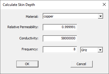
- Select the chosen Material: on the drop-down menu.
- If chosen, edit the material's Relative Permeability:, Conductivity:, or Frequency: by entering new values in the appropriate fields.
- Click OK. The solver calculates the skin depth and enters its value in the Skin Depth field. Accept the calculated values or provide others.
- In Number of Layers of Elements, enter the number of layers to add perpendicular to the object's surface. The skin depth is the total depth of all layers combined. The solver adds an equivalent number of mesh points to each layer (e.g., if HFSS added 10 points to satisfy the Triangle Length Ratio, it adds 10 points to each layer).
- Optionally, provide the length ratio of the surface mesh in Triangle Length Ratio. The default value is set to 400. The solver refines the surface triangle mesh (the faces of the tetrahedra touching the surface) until their edge lengths are less than or equal to a value determined by the formula: Triangle Length Ratio * Skin Depth / Number of Layers of Elements.
- To restrict the number of surface elements added during refinement of faces:
- Select Restrict the Number of Surface Elements.
- Enter the Maximum Number of Surface Elements to be added. When the mesh is generated, the refinement criteria specified is used. If the maximum number of elements is reached, some elements may exceed the requested maximum element length ratio.
Note:By default, Restrict Number of Surface Elements is unchecked to allow the mesher to use symmetry more effectively. Restricting the number of surface elements may affect symmetry but can protect against runaway refinement in specific cases. When Restrict Number of Surface Elements is unchecked, the Maximum Number of Surface Elements is unavailable and provides an estimate of mesh growth.
- If seeding the mesh by region, use the Region Selection area to select one region.
- Click OK.
The procedure is complete.