
Defining a Parametric Antenna Array
A Parametric antenna array is a finite 2D array geometry, which could easily simulate pre-defined layout types (rectangular, elliptical, linear), amplitude/weight types (like Uniform, Hamming) and scan definition methods (scan angles, phase shift).
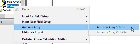
- Click HFSS >Radiation> Antenna Array>Antenna Array Setup... or right click on the Radiation icon in the Project tree and select Antenna Array>Antenna Array Setup...
The Antenna Array Setup window appears.
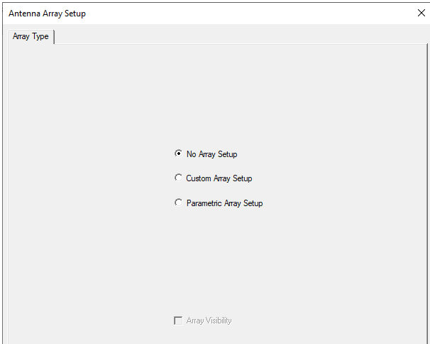
- Under the Array Type tab, select ParametricArray Setup. The enables tabs for Array Geometry and for Array Weight.
- Click the Array Geometry tab.
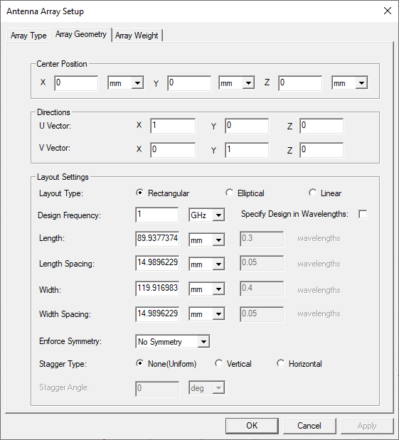
- Under Center Position, enter the xyz-coordinates where the center cell is placed.
- Under Directions, define the lattice vectors:
- To the right of U Vector, enter the vector coordinates in the X, Y, and Z text boxes along which the cells in the U-direction are placed.
- To the right of V Vector, enter the vector coordinates in the X, Y, and Z text boxes along which the cells in the V-direction are placed.
- Under Layout Settings, specify the layout type as Rectangular, Elliptical, or Linear.
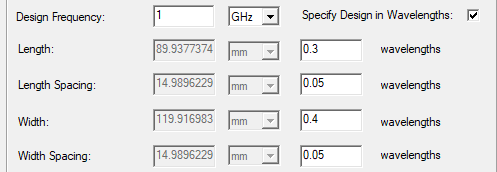
- For Design Frequency,by default, specify the Frequency, Length, Length Spacing, Width, and Width Spacing values, as or check to enable Specify Design in Wavelengths.
Note: The “Design Frequency” is only used for array setup and preview. It will not replace the solution frequency. If a Secondary boundary is used, U / V directions and length / width settings would match lattice vectors when setting up a new parametric array. - For Enforce Symmetry, use the menu to specify No Symmetry, Horizontal Symmetry, Vertical Symmetry, or Horizontal and Vertical Symmetry.
- For Stagger Type, select one of None (Uniform), Vertical, or Horizontal. If you specify a Stagger type, the Stagger Angle field is enabled.
- Click the Array Weight tab.
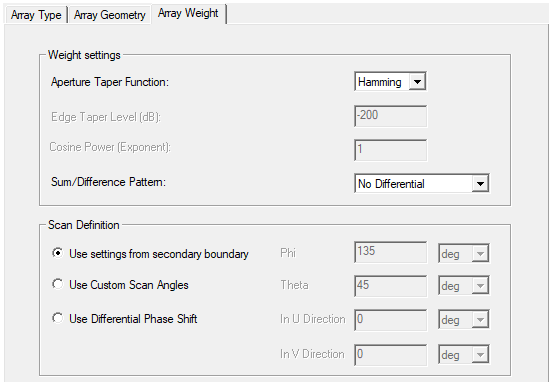
- Under Weight settings, select the Aperture Taper Function from Hamming, Uniform, Cosine, or Triangular. Each selection enables the appropriate parameters:
Hamming and Uniform require a Sum/Difference Pattern as No Differential, Horizontal Differential, Vertical Differential, or Horizontal and Vertical Differential.
Cosine requires Edge Taper Level, and Cosine Power [Exponent], as well as Sum/Difference Pattern.
Triangular requires Edge Taper Level, as well as Sum/Difference Pattern. - Under Scan Definition, either Use settings from secondary boundary, Use Custom Scan Angles as Phi and Theta, or Use Differential Phase Shift in U or V directions.
- Click Apply (with Preview Array Layout checked) to view a representation in the Modeler window, and OK to close the dialog and dismiss the preview.
The Array Geometry parameters will be applied, when far fields are calculated.