
Creating Mesh Animations
You can create mesh animations to evaluate the effect of single variables or parametric sweep variables on the model. Following is the general procedure for creating a mesh animation that varies a part of the model geometry.
Prerequisites:
- You must define at least one variable associated with the geometry before you create a mesh animation.
- You must create a Mesh plot.
Procedure:
- Select the Mesh plot in the Project Manager, right-click in the Modeler window, and
click View> Animate..., or right-click the Mesh plot, and click Animate...
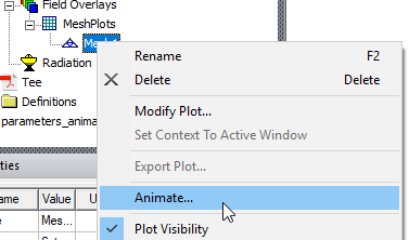
Select the View tab of the ribbon, and click the Animate icon.

If multiple geometries can be varied in the design, the Select Drawing dialog box appears; proceed to step 2. If only one geometry is variable, proceed to step 3.
- In the Select Drawing dialog box, select the object that you want to animate.
Note:
If previous animations have been created for this project, the Select Animation dialog box will appear. Selecting an existing animation from that list starts it when you click OK. Click Edit... to open the Modify Animation Setup dialog box. If no existing animation setup is acceptable, select New and continue below.
The Create Animation Setup dialog box appears.
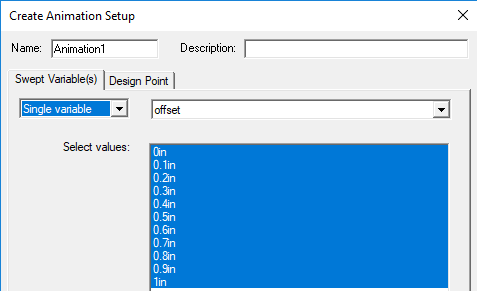
- In the Create Animation Setup dialog box:
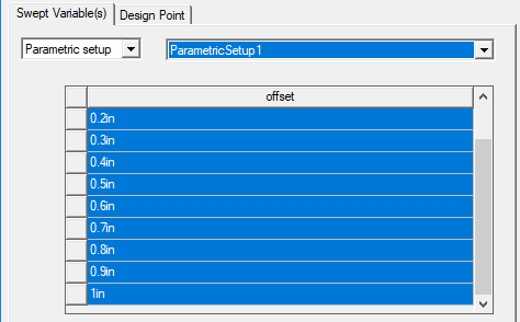
- Select the Single variable, or Parametric setup, or DOE setup if available. If multiple single
variables are available, you can select from a drop-down menu. If one or more Parametric setups exist, you can choose
from the drop-down menu. The values for the selected parametric setup are displayed.
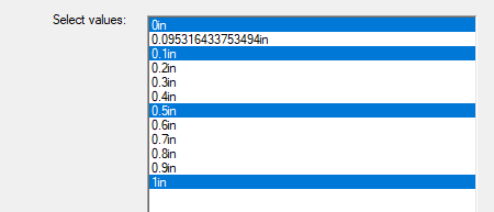
- If desired, specify the values to include in the animation. Selected values are highlighted.
- If the design has multiple project or intrinsic variables, you use the Design Point tab to set the values of the non-animated variables.
- Select the Single variable, or Parametric setup, or DOE setup if available. If multiple single
variables are available, you can select from a drop-down menu. If one or more Parametric setups exist, you can choose
from the drop-down menu. The values for the selected parametric setup are displayed.
- Click OK.
The animation begins in the view window. It will display one frame for each variable value.
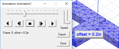
The Animation control panel lets you to stop, restart, and control the speed and sequence of the frames.