
Imprinting an Object
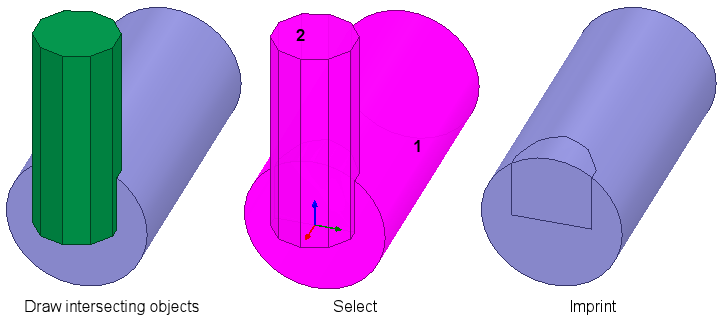
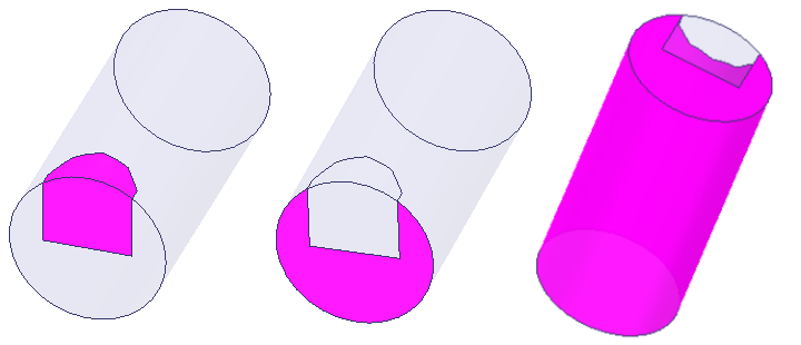
The Boolean > Imprint command lets you imprint the geometry of one object upon another. For example, you could draw a polyhedron intersecting a cylinder, and then imprint the intersecting lines on the cylinder. This process splits the larger face into two or more faces, with the intersecting lines representing the edges of the imprinted face. The original face is cut so that it no longer extends into the imprinted area.
Imprinting is often an essential capability for finite element analysis. It enables a boundary or excitation to be applied to the exposed area of a model face while excluding it from areas of intersection with other parts. One example is a thermal analysis where convection is applied to the exposed surfaces of a heat sink. The area in contact with a semiconductor (the source or heat) is not exposed to ambient air and should not receive a convection boundary. In this case, you would imprint the semiconductor on the heat sink, producing a separate heat sink face in the contact area. This face is excluded from the selection set when applying the convection boundary.
You can select the faces of the imprinted surface separately and assign properties as needed.
To imprint one object with another:
- Select the intersecting objects.
- From the menu bar, click Modeler > Boolean > Imprint... or, on the Draw ribbon tab, click the Imprint icon:
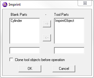
- Optionally, select Clone the tool objects before operation to retain the tool part. Otherwise, only its imprint on the blank part will remain.
- Click OK to close the dialog box and perform the Boolean imprinting.
.png)
The Imprint dialog box displays in which you designate which objects are the Blank Parts, and which the Tool Parts. If necessary, you can select the objects in lists, and use the arrow keys to move them. If desired, you can clone the tool objects before the imprint operation.
The History Tree retains the ImprintObject command and the Create<object> command for the imprinted tool object:
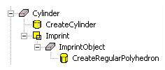
If you select the Imprint command in the History tree, you can suppress the command via the docked Properties window. If you select the Create<object> icon, you can edit the properties of that object. The changes you apply carry over to the imprinting operation, modifying the imprinted face accordingly.
In the 3D Modeler > Operation section of the General Options, you can also enable the Automatically imprint wrapped sheets option to automatically perform an Imprint operation command after executing the Modeler > Surface > Wrap command.