
Imprint Projection commands
The Boolean> Imprint Projection commands lets you project the form of a sheet object onto the face or faces of another object (either solid or sheet). The receiving object faces can be flat, curved, or faceted.
If the receiving surface is curved or inclined, and you choose to project Along Normal direction, the dimensions of the projection are affected. The reason is that the projection direction is normal to the curved or inclined face of the receiving object and not normal to the object being projected.
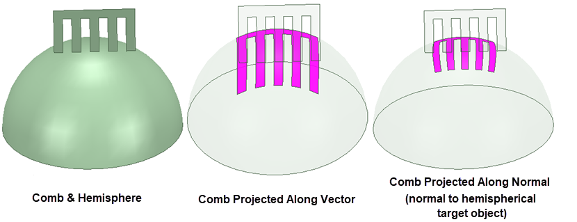
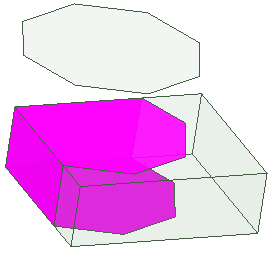
The projected shape will wrap around the target object, from the face nearest to the center of the imprinting area and extending to the adjacent target object faces:
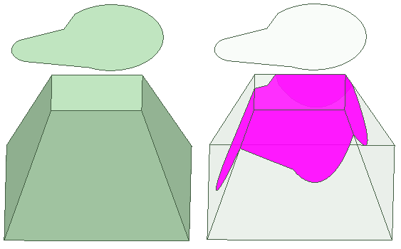
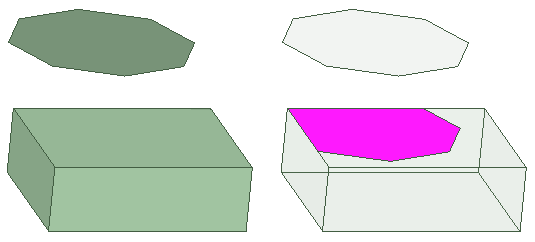
If the projection of the imprinting object extends beyond the extents of the receiving object, the imprinted shape is truncated:
You can select the imprinted faces on the target object separately, and perform subsequent operations (such as creating sheet objects from the faces, assigning boundaries or excitations, or selecting for field overlays).
To perform an Imprint Projection:
- If you want to preserve the tool object that will be imprinted on the target object, use one of the following methods:
- Copy the tool object to the clipboard so that you can paste it back into the model after the imprinting operation.
- In the 3D Modeler> Operation section of the General Options, select the Clone tool objects before projecting option.
- Select the projecting and target objects.
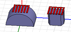
- From the menu bar, click Modeler> Boolean> Imprint Projection> Along Normal or Modeler> Boolean> Imprint Projection> Along
Direction...
- If you select Along Normal, the projection occurs along the direction normal to the target faces and the operation is completed immediately. Imprinting occurs only on target faces visible from the imprinting object's point of view.
- If you select Along Direction, you must specify two points that define the imprinting vector direction (step 3 below). Once you have done this, you see a dialog box for specifying the projection Distance. This option allows you to limit the projection distance so that only near faces are affected. Unlike the Along Normal option, the Along Direction option can imprint onto the target object faces that are not visible from the imprinting object's point of view (that is, those on the opposite side of the target object):
- If performing an imprint projection operation using the Along Direction option:
- Specify the imprinting vector direction. You can click in the Modeler window or use the coordinate entry text boxes in the Status Bar.
The Project along direction dialog box appears:
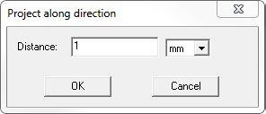
- Specify the maximum projection Distanceand select the length unit from the drop-down menu.
- Click OK.
The dialog box closes and the Boolean imprinting operation is performed.
- Specify the imprinting vector direction. You can click in the Modeler window or use the coordinate entry text boxes in the Status Bar.
After you perform the imprinting, the History Tree shows the ImprintProjection command and the create command for the imprinted object.
If you select the Imprint Projection command in the History Tree, you can suppress the command via the docked Properties window. If you select the Create<object> icon for the object, you can edit the properties of that object. The changes applied to the object carry over to the imprinting operation.