
Drawing a SubRegion
The Modeler allows you to define a subregion that encompasses a set of objects inside previously defined region. Like regions, subregions automatically resize if the objects contained in these subregions change. You can create nested subregions, and reassign the content of a subregion.
To draw a sub-region in the current project:
- Select the parts of components that you want to include in a subregion.
- From the menu bar, click Draw >
 SubRegion:
This displays the SubRegion dialog box.
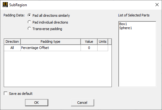
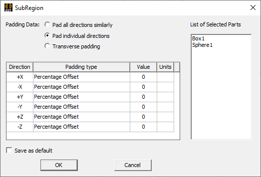
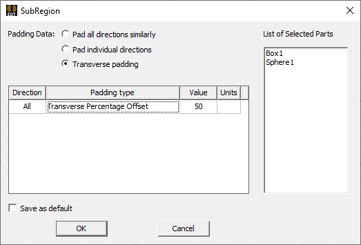
- For the Padding data, click the Padding Data radio button as Pad all directions similarly, Pad individual directions, or Transverse padding.
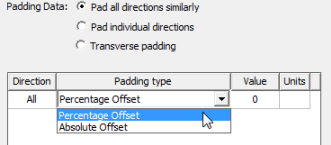
Selecting Pad all directions similarly leaves the Padding type field as requiring a single value that affects all directions. In this case, you can specify the Padding type by selecting Percentage Offset or Absolute Offset from the drop-down menu.
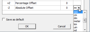
If you select Absolute Offset, you also specify the units by selecting from a drop-down menu.
Selecting Pad individual directions displays the Padding Percentage as a table of Positive and Negative X,Y, and Z coordinates, permitting you to specify padding for each direction. In this case, you can specify the Padding type by selecting Percentage Offset or Absolute Offset or Absolute Position from the drop-down menu.
Selecting Transverse padding means that padding in one direction is controlled by dimensions in other two directions. Each direction (for example, X) is padded with user-specified percentage of diagonal length of the other two directions (Y and Z).
- Specify the Padding values in the fields and select the units from the drop-down menu.
- If desired, select the check box to save the values as Default.
- Click OK to close the dialog and create the sub-region.
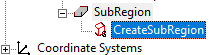
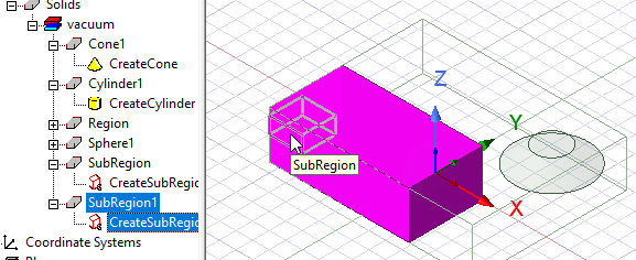
The sub-region is drawn, selected, and displayed in the History tree. It is created using the current coordinate system.
Additional SubRegions and Nested SubRegions.
If you create additional sub-regions, these appear in the History Tree.
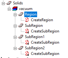
SubRegions can contain other SubRegions, that is, SubRegions can be nested.
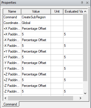
Properties for SubRegions
The Properties dialog for the Create SubRegion icon in the History tree shows the coordinate system and Padding values.
The Properties dialog for the selected model lists attributes tab including Name, Material (Default, vacuum), Solve inside, Orientation, Model, Color, Display Wireframe, and Transparency. You can edit all of these values.
You can use modeling operations on these sub region parts with following rules
-
Geometry of non-subregion parts should not depend on sub-region parts. That is, sub-region parts should not be allowed to be used as a tool, not even after cloning them
-
Simple local operations like face move, fillet, and arrange operations should be allowed on sub-region parts.
Global region should take the sub-regions into account in its computation.
Sub-Regionscan be included in components.