
Drawing a Region
To draw a region encompassing the objects in the current project:
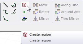
- From the menu bar, click Draw >
 Region or, on the Draw ribbon tab, click the Create region icon:
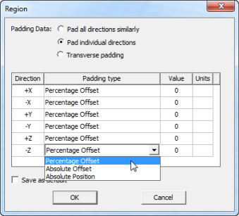
This displays the Region dialog box.
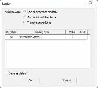
- For the Padding data, click the Padding Data radio button as Pad all directions similarly, Pad individual directions, or Transverse padding.
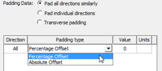
Selecting Pad all directions similarly leaves the Padding type field as requiring a single value that affects all directions. In this case, you can specify the Padding type by selecting Percentage Offset or Absolute Offset from the drop-down menu.
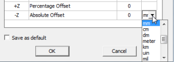
If you select Absolute Offset, you also specify the units by selecting from a drop-down menu.
Selecting Pad individual directions displays the Padding Percentage as a table of Positive and Negative X,Y, and Z coordinates, permitting you to specify padding for each direction. In this case, you can specify the Padding type by selecting Percentage Offset or Absolute Offset or Absolute Position from the drop-down menu.
Selecting Transverse padding means that padding in one direction is controlled by dimensions in other two directions. Each direction (for example, X) is padded with user-specified percentage of diagonal length of the other two directions (Y and Z).
For a single antenna element, something that is radiating does not radiate with reasonable efficiency until it is lambda/2 in length, L, and it radiates in the direction transverse to the dimension L. So we get the dimension L from the region command and pad it 50% which would then correspond to the lambda/4 of the frequency at which the device is lambda/2 but only in the direction in which energy radiates, the transverse direction.
A basic example is a thin resonate dipole oriented in z. There is zero radiation in the z-direction so no need to pad the abc in that direction since no energy goes in that direction. But in X and Y transverse to the length L we do need to pad lambda/4 (the 50% setting) because it is that direction that the device radiates.
- Specify the Padding values in the fields and select the units from the drop-down menu.
- If desired, select the check box to save the values as Default.
- Click OK to close the dialog and create the region.
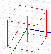
The region is drawn, selected, and displayed in the History tree. It is created using the current coordinate system. The Properties dialog for the Create Region icon in the History tree shows the coordinate system and Padding values. The Properties dialog for the selected model lists attributes tab including Name, Material (Default, vacuum), Solve inside, Orientation, Model, Color, Display Wireframe, and Transparency. You can edit all of these values.
If you try to create a region that does not contain all of the objects in your model, the modeler automatically expands the region to cover all objects. The region also updates automatically as your geometry changes.
Only one region can be created for a single project using the Draw > Region command. If you try to create a second region, the Properties window appears for the existing region, allowing you to change operation parameters and attributes.