
Assign Lumped Ports for Terminal Solutions
After making selections for assigning a lumped port, and selecting HFSS>Excitations>Assign>Lumped Port, you see the Reference Conductors for Terminals dialog.
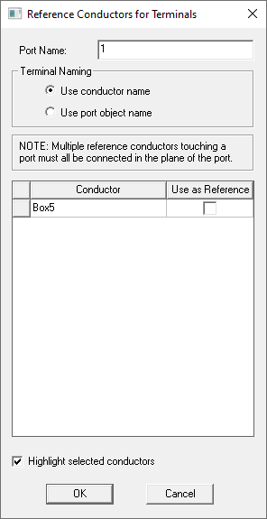
For details, see Reference Conductors.
As with lumped ports for modal solutions, while assigning lumped ports for terminal solutions, you will be prompted to set the complex full port impedance. The real part (resistance) must be positive. The imaginary part (reactance) must be non-zero if the resistance is zero. There are three ways to assign lumped ports for terminal solutions.
- Selecting a Face or Sheet
- Selecting Two Linear Edges that Do Not Intersect
- Selecting a Face and a Linear Edge
Selecting a Face or Sheet
The steps are as follows:
- Select
a surface to which you want to assign the port and click HFSS>Excitations>Assign>Lumped
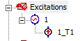
Port to bring up the Reference Conductors dialog. After you OK the Reference Conductors dialog, you see the Port assigned in the Project tree.
- Double click on the Port to open Lumped Port: General dialog box.
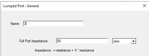
- Define the complex Full Port Impedance
in the text field.
The format is "<real_part> + <complex_part>*i ohm", for example 50ohm + (-5ohm) * 1i Note:
The reference impedance is meant to represent the component modeled by the lumped port. You can assign a variable to these values, (for example " resistance + (reactance) * 1i"). This variable can be dependent on the frequency, which allows use of a dataset for frequency dependent impedance, (for example, pwl(ds1,freq) + (pwl(ds2,freq)) * 1i).
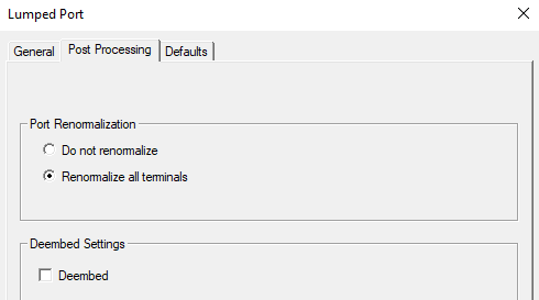
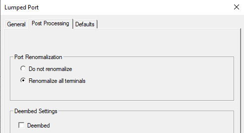
- Click the Post Processing tab to see the Post Processing settings.
For designs with only lumped ports or a combination of lumped and circuit ports, the Advanced Solution Setup, Options tab includes an option to use Enhanced low frequency accuracy.
Selecting Two Linear Edges that Do Not Intersect
A terminal will be assigned to the first edge selected.The steps are as follows:
- Set the selection mode to Edge or Multi, select the edge to which you want to assign the port and click HFSS>Excitations>Assign>Lumped
Port to bring up the Reference Conductors dialog. After you OK the Reference Conductors dialog, you see the Lumped Port: General dialog box.
- Define the complex Full Port Impedance
in the text field.
The format is "<real_part> + <complex_part>*i ohm", for example 50ohm + (-5ohm) * 1i Note:
The reference impedance is meant to represent the component modeled by the lumped port. You can assign a variable to these values, (for example " resistance + (reactance) * 1i"). This variable can be dependent on the frequency, which allows use of a dataset for frequency dependent impedance, (for example, pwl(ds1,freq) + (pwl(ds2,freq)) * 1i).
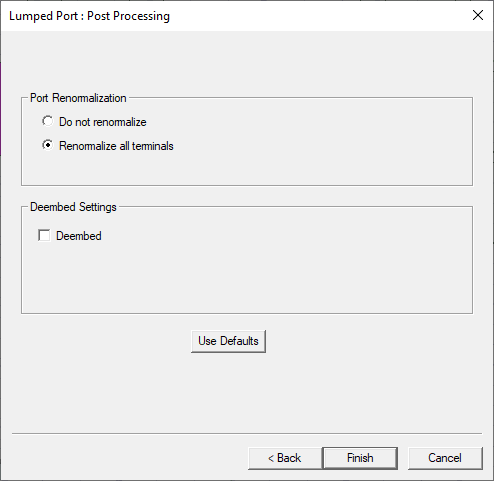
- Click Next. The Post Processing settings appear.
-
Click Finish to see the Port in the Project tree.
For designs with only lumped ports or a combination of lumped and circuit ports, the Advanced Solution Setup, Options tab includes an option to use Enhanced low frequency accuracy
Selecting a Planar Face and a Linear Edge
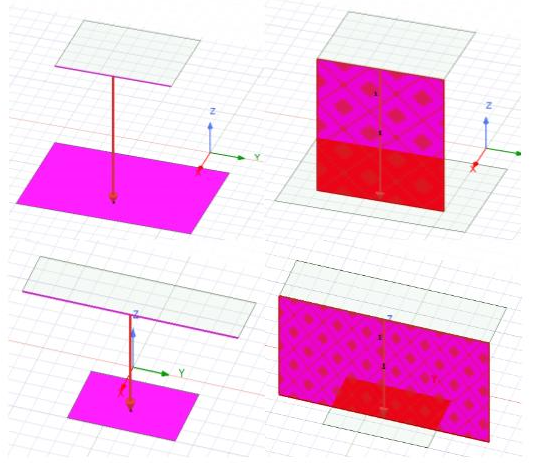
You can select exactly one linear edge and one planar face and create a lumped port to launch the dialog. As to the associated sheet created for the lumped port, if the edge intersects with the face, or the edge is vertical to the face, or most part of the edge cannot be projected on the face, an error message is issued. Otherwise, the 2 endpoints of the edge and the 2 projected point of the face are used to create a sheet that is vertical to the selected face.
The steps are as follows:
- Select
a face and a linear edge where you want to assign the lumped port and click HFSS>Excitations>Assign>Lumped
Port to bring up the Lumped Port: General dialog box.
- Define the complex Full Port Impedance
in the text field.
The format is "<real_part> + <complex_part>*i ohm", for example 50ohm + (-5ohm) * 1i Note:
The reference impedance is meant to represent the component modeled by the lumped port. You can assign a variable to these values, (for example " resistance + (reactance) * 1i"). This variable can be dependent on the frequency, which allows use of a dataset for frequency dependent impedance, (for example, pwl(ds1,freq) + (pwl(ds2,freq)) * 1i).
- Click Next. An integration line is automatically drawn, and the Post Processing settings appear.
-
Click Finish to see the Port in the Project tree.
For designs with only lumped ports or a combination of lumped and circuit ports, the Advanced Solution Setup, Options tab includes an option to use Enhanced low frequency accuracy.