Placing Components in Schematics
To facilitate the copying of design materials, drag and drop both designs and components on the Project Manager window to the Schematic Editor. In particular, drag and drop into a schematic:
- A design on the Project Manager window
- A component on the Project Manager window Definitions folder
- A component on the Components tab in the Component Libraries window
Components can also be placed by clicking on a component symbol in the Symbols tab of the Component Libraries window. Then click in the Schematic window to place to place the component.
You can drag and drop one or more copies of a component into a schematic. Alternately, right-click on a component and select Copy, then right-click in the schematic and select Paste (or use the Ctrl +C and Ctrl +V keyboard commands).
If Multiple Placement is activated for components in the Schematic Options window, place multiple instances of a component in the schematic by clicking at multiple locations. To stop placing components during multiple placement, do either of the following:
- Press Enter, the spacebar, Backspace, or Esc on your keyboard.
- Right-click , then select Place and Finish, Finish, Cancel, or Back.
To place a component:
- Select the schematic that contains the component that you places.
- Next, select and place the component in the schematic using one of the methods described in the Note above. Inside the schematic window, the cursor is accompanied by the component symbol for placement.
- You can rotate a component before placing it by repeatedly pressing R on your keyboard. Each press rotates the component 90º counterclockwise.
- You can flip the component left-to-right by pressing X.
- You can flip the component top-to-bottom by pressing Y.
For components with physical layers, the Merge Layers window may appear. See the Merge Layers window topic for further information.
- The first time a component project is placed, entries for it are added in the Component Libraries window's Most Recently Used and Project Components headings. To save time as your work progresses, place new instances of a component by double-clicking these icons in the Components tab or selecting the symbols in the Symbols tab. Please note that for security reasons, encrypted components are not saved in the Most Recently Used list or the Favorites list.
- To ensure electrical connectivity among schematic elements, the pins of placed components snap to a 100-mil (2.54-millimeter) grid. This snapping cannot be deactivated, and the spacing of the connectivity grid cannot be adjusted.
- To move an existing component, select
and drag the component to a new position. In-place wiring to the component
is automatically adjusted. To retain the in-place wiring, hold down Alt as you drag the component to a new position.
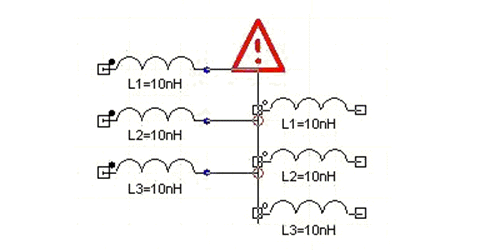
Please note that when dragging a component to a new position, if the wires attached to it make an unintended connection, a red exclamation mark is displayed as a warning. The following figure illustrates that red circles are used to indicate where connections is made and the exclamation point warns that there may be a connection that is not what you intended.