


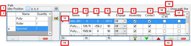
Figure 12.120: Path Data in the Placing tab
| Parameter | Description |
| 1. Idler position | This represents idler position. The idler position is reference position in Links (Track). |
| 2. List of path file | This is the group in order to model the Path of Links (Track). The source of group is file in work navigator. If there are Path files in work navigator, those file is added
the group. "Name" is a file name. "Quantity" is the number that adds to grid data of the Path. is used to add file from other folder. is used to add file from other folder. is used to delete file information in the group. is used to delete file information in the group. is used to add selected file information to grid data of the Path. is used to add selected file information to grid data of the Path. |
| 3. Name | This is the name of the Path. |
| 4. Di | This is the distance from previous Path to current Path in the direction of longitudinal. For example, If user builds Links (Track) in XY plane, the direction of longitudinal is X-axis. |
| 5. Hi | This is the distance from previous Path to current Path in the direction of vertical. For example, If user builds Links (Track) in XY plane, the direction of vertical is Y-axis. |
| 6. Ri | This is an Assemble radius that is a loaded data in the property of Path file. |
| 7. Engage |
This represents wrapping method of Path. There is Off, Pin and Center. For more information, refer to Placing Tab. |
| 8. Assembly | If this is checked, each Path is used when Segment is wrapped. If not, each Path is not used when Segment is wrapped. |
| 9. Contact | If this is checked, the contact geometry of Path is added to the table for contact between Path and Segment. If not, the contact geometry of Path is not added to the table. |
| 10. Direction (CW) | This represents wrapping direction. There is CCW (Counter clockwise) and CW (Clockwise). Refer to Placing Tab for more information. |
| 11. Sprocket | This represents the effect of gap when Path is wrapped by Segment. If this is checked, Segment length is used original value when the position and orientation of Segment is calculated. If this is unchecked, Segment length is used modified value when the position and orientation of Segment is calculated. But Segment length is always used modified value between Paths. Refer to Placing Tab for more information. |
| 12. Draw path line | This represents operation that the tangent line is drawing between Paths. |
| 13. Grid data | This represents the property of the Path. |
| 14. Multi editable control | This is used when many properties of Path modify in a lump. |
| 15. Modification controls of Path | This is used to add the Path through pick operation in working window. |