


Attach the above components by creating the following assemblies:
Attach the external gearset and bearings to the flexible shaft, as follows:
Select the Shaft_Flexible object in the Motion tree.
In the Details panel, under > , click .
In the External Gears dialog, click the
 button to add
section data as follows:
button to add
section data as follows:Parameter Value Gear External Gear Set/DrivingRemote Point RP_S_M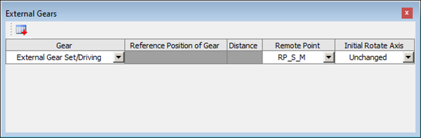
In the Details panel, under > , click .
In the Details panel, under > , click .
In the Rolling Bearings dialog, click the
button to add
section data as follows:Bearing Raceway Remote Point B6203_1Inner RacewayRP_S_RB6203_2Inner RacewayRP_S_L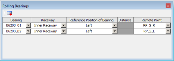
In the Details panel, under > , click .
Attach the external gearset and bearings to the flexible shaft, as follows:
Select the Shaft_Beam object in the Motion tree.
In the Details panel, under > , click .
In the External Gears dialog, click the
button to add
section data as follows:Parameter Value Gear External Gear Set/DrivenReference Position of Gear LeftDistance 20mm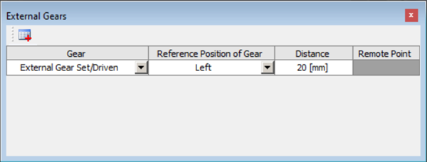
In the Details panel, under > , click .
In the Details panel, under > , click .
In the Rolling Bearings dialog, click the
button to add
section data as follows:Bearing Raceway Reference Position of Bearing Distance B61805_1Inner RacewayLeft0mmB61805_2Inner RacewayLeft88mm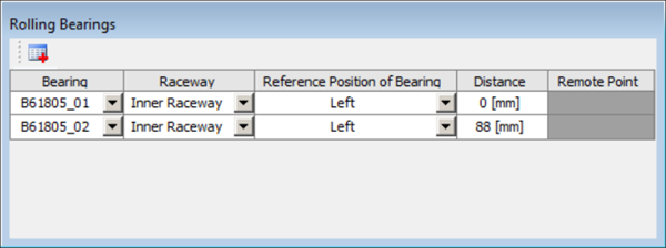
In the Details panel, under > , click .
Attach the bearings to the housing, as follows:
Select the Housing object in the Motion tree.
In the Details panel, under > , click .
In the Rolling Bearings dialog, click the
button to add
section data as follows:Bearing Raceway Remote Point B6203_1Outer RacewayRP_H_R_01B6203_2Outer RacewayRP_H_L_01B61805_1Outer RacewayRP_H_R_02B61805_2Outer RacewayRP_H_L_02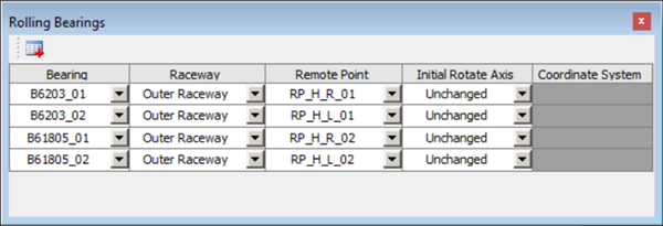
In the Details panel, under > , click .
Create two fixed joints on the Housing as follows:
Expand the Model branch in the Project tree and right-click Connections.
Select > .
Define two fixed joints as shown below.
Name Connection Type Type Scoping Method Remote Points Fixed_Joint_01Body-GroundFixedRemote PointRP_H_R03Fixed_Joint_02Body-GroundFixedRemote PointRP_H_L03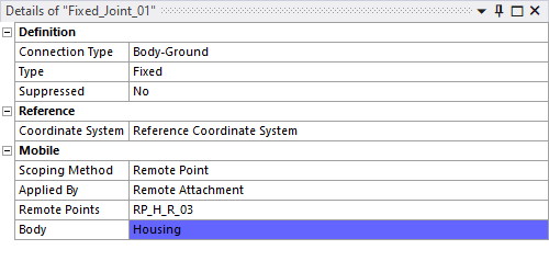
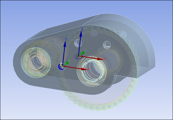
In the Connections > Joints branch, expand the each of the new fixed joints and select the Reference Coordinate System object (see below).
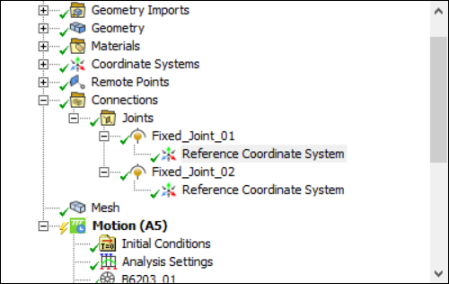
In the Details panel, under Origin, set Define By to and use the selection tool (CTRL+F) to select the face corresponding to each joint (see below).
Update the two shaft bodies as follows:
Right-click the Shaft_Flexible object in the Motion tree.
Select .
Right-click the Shaft_Beam object in the Motion tree.
Select .
Right-click the Housing object in the Motion tree.
Select .
Right-click the External Gear Set object in the Motion tree.
Select .