
DC IR and Icepak Simulation on Hierarchical Designs
DC IR and Icepak simulations support hierarchical designs, enabling accurate simulation of electrical and thermal behavior across stacked components such as packages, boards, and nested sub-designs. These solvers operate on unified layouts that may include package-on-PCB assemblies or package-on-package stacks exported from SIwave.
This feature is currently in beta. Beta features must be activated prior to use. Refer to Activating the ECAD-ECAD Hierarchical Design Beta Feature for instructions. Refer to Hierarchical Design.
If the design originates in SIwave, it can be exported to Electronics Desktop for full modeling of placement and connectivity. Once imported, simulations can be launched directly on the hierarchical structure.
-
Start with a hierarchical layout in SIwave or Electronics Desktop.
-
Export the layout to Electronics Desktop using Export HFSS 3D Layout Project or Icepak Export, if starting from SIwave.
-
Run DC IR or Icepak simulations, which support hierarchical design.
DC IR computes voltage drop and current flow across the full structure, while Icepak models temperature distribution based on power dissipation. These solvers can be coupled iteratively to refine results using temperature-dependent material properties. Together, they provide a comprehensive solution for analyzing power integrity and thermal performance in complex assemblies.
SIwave Export to Electronics Desktop
SIwave cannot simulate coupling between non-coupled stacked packages and the board. Exporting these configurations from SIwave to Electronics Desktop enables full modeling of hierarchical assemblies that include physical placement but lack direct coupling in SIwave. In SIwave, non-interacting stackups are used to represent stacked configurations without simulating the electrical interaction between them. When exported to Electronics Desktop, these configurations are instantiated as a true hierarchical design in which all components are physically positioned and electrically connected. This allows DC IR and Icepak simulations to operate on the complete structure, capturing power and thermal behavior across the full stackup.
Alternatively, use the scripting command oDoc.ScrExportAEDT() to export the design. All hierarchy levels will be populated, and packages mounted in multiple locations will be represented as single designs with multiple instances.
Icepak simulations impose a configuration constraint: each cell in the hierarchy must be instantiated only once. To instantiate multiple copies, the cell must be duplicated so that each instance originates from a unique source. This restriction does not apply to DC IR. When exporting from SIwave using the Icepak export option, this duplication is handled automatically. Other EDB-based exports may allow multiple instances and may require manual adjustment for Icepak compatibility.
DC IR Simulation on Hierarchical Designs
DC IR simulation on hierarchical layouts enables accurate modeling of voltage drop and current flow across complex assemblies that include multiple physically stacked sub-designs. In this workflow, users define voltage and current sources across packages, boards, and nested components, allowing the solver to compute power distribution throughout the entire structure. The simulation accounts for the electrical connectivity between sub-designs, including interposers, solder balls, and shared nets, and produces a unified solution that reflects the full electrical behavior of the system. This approach supports advanced power integrity analysis in multi-component layouts without requiring flattening or manual merging of designs.
- Open a hierarchical layout in Electronics Desktop (e.g., package on PCB).
- Run a DC IR simulation on the top-level design.
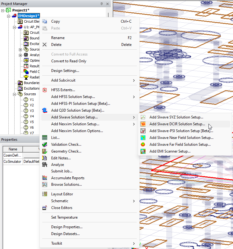
- Define current and voltage sources:
- Voltage sources define where voltage is applied (e.g., power rails).
- Current sources define where current is drawn (e.g., IC pins).
The software allows duplicate names across sub-designs, but the simulation will fail due to naming collisions.
- Ensure all sources across all sub-designs have unique names by doing either of the following:
- From the Project Manager window, expand the Project > active design > each sub-design > and Sources. Then right-click each source, select Rename, and enter a new name for the source.
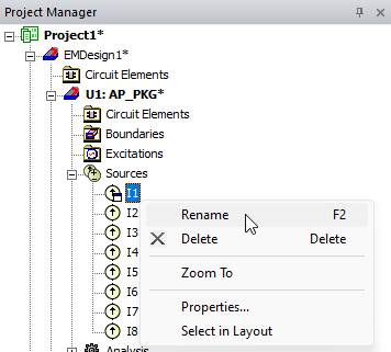
- Promote sources from sub-designs to the top-level design. During promotion, sources with duplicate names will be renamed:
- From within the Layout Editor, right-click the sub-design and select DCIR > Create Current Sources on Components to open the Create Ports window.
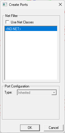
- From the Create Ports window, do the following:
From the Net Filter area, check the Use Net Classes box, if applicable.
Select a net from the list.
From the Port Configuration area, select a Type of port from the drop-down menu.
- Click OK to promote the connected sources to the top-level design.
Before – Sources are spread across two levels of the hierarchical design.
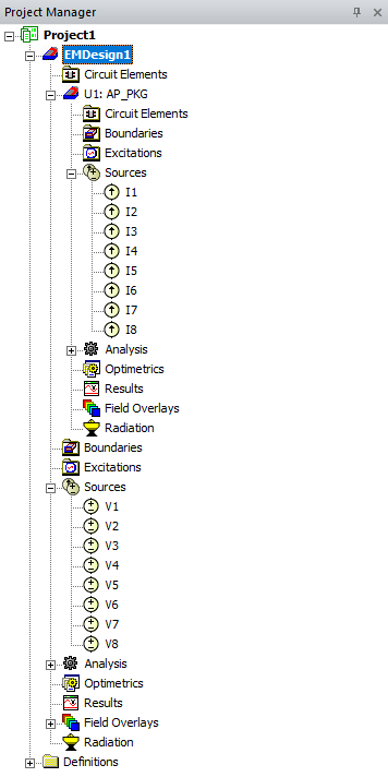
After – Sources are shown on the top level of the hierarchical design.
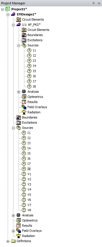
- From within the Layout Editor, right-click the sub-design and select DCIR > Create Current Sources on Components to open the Create Ports window.
- From the Project Manager window, expand the Project > active design > each sub-design > and Sources. Then right-click each source, select Rename, and enter a new name for the source.
Source promotion is strongly recommended for all DC IR and Icepak simulations. It ensures name uniqueness across the hierarchy and prevents simulation failures due to naming collisions. This is especially important when a cell is instantiated multiple times, as each instance would otherwise create duplicate source names. In cases where all source names are already unique and no cells are reused, promotion is not strictly required, but it remains a best practice.
Two-Way Coupled Icepak Simulation
Two-way coupled simulation between DC IR and Icepak enables thermal-electrical feedback modeling across hierarchical designs. In this workflow, the electrical power distribution computed by DC IR is used as the heat source input for Icepak, which in turn calculates the resulting temperature distribution. Because electrical conductivity is temperature-dependent, the updated temperature profile is then used to refine the material properties in the DC IR model. This feedback loop continues for several iterations, allowing both solvers to converge on a solution that reflects the mutual influence of electrical and thermal behavior.
- Set a uniform temperature and enable feedback in the HFSS 3D Layout design.
- Run a DC IR simulation to compute power distribution.
- Add an Icepak design to the active project and insert a PCB-native component.
- Add two-way coupling to the Icepak design.
- Run an Icepak simulation to compute temperature distribution.
- Repeat DC IR and Icepak solves for 3–4 cycles until convergence.
This iterative process ensures accurate modeling of temperature-dependent electrical behavior. Refer to Coupling SIwave DC IR Loss. It is fully supported on hierarchical designs, including those with multiple packages, nested components, and virtually mounted structures.
Coordinate Systems and Hierarchy Navigation
Coordinate systems provide the structural framework for organizing components in hierarchical designs. Each object or sub-design is positioned within either a global or relative coordinate system, which defines its origin, orientation, and nesting behavior. The global coordinate system serves as the fixed reference for the entire layout, while relative coordinate systems allow localized control over placement and rotation. Users can navigate between hierarchical levels using Push Down and Pop Up commands, which activate different coordinate contexts and expose the contents of nested designs. Grouping objects into a relative coordinate system enables modular editing and reuse, while ungrouping dissolves the local context and returns objects to the parent layout. These tools streamline layout management and support precise control over component positioning, especially in multi-level assemblies. Refer to Coordinate Systems.
- The Global coordinate system is fixed and cannot be edited.
- Relative coordinate systems are defined per component or sub-design and can be nested.
- Use Push Down and Pop Up to navigate between hierarchical levels.
- Use Group Into CS and Ungroup to manage component placement.
Coordinate system hierarchy affects layout navigation and component grouping, but does not directly impact DC IR or Icepak simulation fidelity unless sources or components are hidden or misaligned.
Validation and Visualization
Simulation results can be validated using field overlays and post-processing tools in Electronics Desktop. The Create Field Plot window supports visualization of layers from linked hierarchical designs. The Layout Editor presents the full design with stacked packages, and the Project Manager window displays nested hierarchy with multiple instances of the same linked design. Refer to Postprocessing and Generating Reports.
Activating the ECAD-ECAD Hierarchical Design Beta Feature
Follow these steps to enable the ECAD-ECAD hierarchical design beta feature.
-
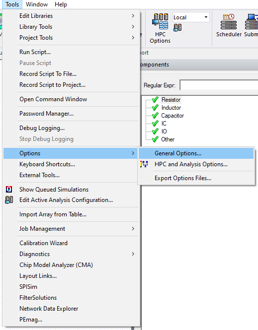
From the Tools menu, select Options > General Options to open the Options window
-
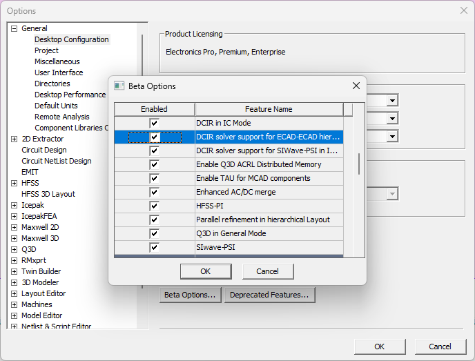
Expand General > Desktop Configuration and click Beta Options to open the Beta Options window
-
Scroll down to the HFSS 3D Layout section and check the box adjacent to DC IR solver support for ECAD-ECAD hierarchy.
-
Click OK to close the Beta Options window.
-
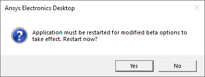
Click OK to close the Options window and open a prompt to restart the software. Users may be asked to save their work.
-
Click Yes to restart immediately.
-
After restarting the software, simulation of hierarchical design will now function as described in the previous section.
The procedure is complete.