
Adding Sources, Probes, and Terminals
The DC IR workflow wizard’s Configure DC IR Analysis window can be used to generate any of the new element types attached to pin groups of existing components. Alternatively, the new elements can be generated from the Layout ribbon.
Both source types (voltage or current) and voltage probes are modeled as two terminal elements, similar to circuit ports, and are generated in a similar way. Sources can be connected to padstack instances, pin groups, user-specified points in the model space, or components. Refer to Creating Sources on Components.
Adding Voltage Sources, Current Sources, and Voltage Probes
The following example explains how to add a voltage source to the project. Complete the same steps to add as many voltage sources, current sources, voltage probes, or DC terminals as necessary.
DC terminals are not currently supported within the IC Mode environment. The terminal icon will not appear in either the menu or ribbon.
- From the Layout Editor, do one of the following to add a voltage source, current source, voltage probe, or DC terminal.
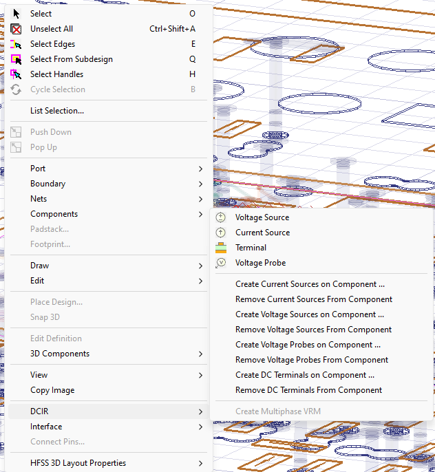
- From within the design area, right-click and select the appropriate element.
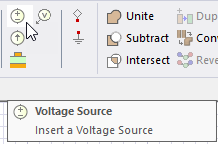
- From the Layout ribbon, select the appropriate element.
Note: DC terminals can also be attached to pin groups or pins. Select a pin group or pin, then click the Terminal icon. A DC terminal is generated on each selected item that does not already have an associated terminal of some kind.Element properties can be edited in the Properties window.
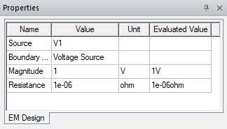
Or right-click the source within the Project Manager window and select Properties to edit from within the source's respective Properties windows.
- From within the design area, right-click and select the appropriate element.
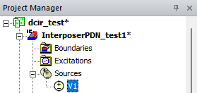
- Click the location where you want to place the element. The element appears in the Project Manager window (i.e., under DC Terminals or Sources).
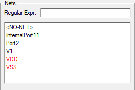
The element also appears in the Nets window (e.g., V1).
Element properties can be edited in the Properties window.
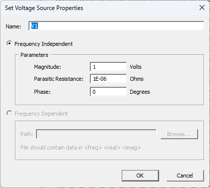
Or right-click the source within the Project Manager window and select Properties to edit from within the element's respective Properties windows.
Creating Sources on Components
From the Layout tab, the following commands are available for managing sources, probes, and terminals. These options allow you to create or remove elements directly on components, ensuring accurate setup for DC IR analysis and hierarchical simulations.
-
Create Current Sources On Component – Generate current sources attached to the selected component. Refer to DC IR and Icepak Simulation on Hierarchical Designs.
-
Remove Current Sources From Component – Delete existing current sources from the selected component.
-
Create Voltage Sources On Component – Generate voltage sources attached to the selected component.
-
Remove Voltage Sources From Component – Delete existing voltage sources from the selected component.
-
Create Voltage Probes On Component – Add voltage probes to the selected component for monitoring potential.
-
Remove Voltage Probes From Component – Delete voltage probes previously added to the selected component.
-
Create DC Terminals On Component – Generate DC terminals on pins or pin groups of the selected component.
-
Remove DC Terminals From Component – Delete DC terminals from the selected component.
-
Create Multiphase VRM – Refer to Viewing and Creating VRMs.