
Terminal Characteristic Impedance Matrix
Consider the situation illustrated below. A 3D structure with one multi-mode waveguide port is loaded by an N-port matrix impedance Z. The structure contains internal sources, which generate outgoing waves that exit through the waveguide port and strike the impedance Z. If Z does not match the impedance of the waveguide in some sense, a reflection will occur from this load and will return to the 3D structure, where it is interpreted as an incident wave.
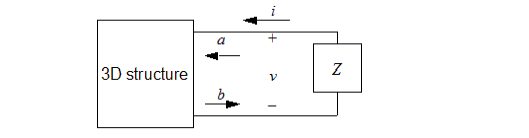
An optimal choice of Z will prevent any reflections from the load returning as an incident wave a. Note that the circuit equations at the load are v = -Zi (the minus sign is due to the sense of the current i). By replacing the voltages and currents with their modal expansions, the voltage becomes
|
|

|
(1) |
Rearranging this to isolate a and b, it is determined that:
|
|

|
(2) |
Now notice that if we select T = ZU ; the incident wave a vanishes. Corresponding to this condition is an "optimal" choice Z0 for the impedance Z:
|
|

|
(3) |
Z0 is the terminal characteristic impedance matrix for the multi-mode waveguide port. This value of impedance will completely absorb any linear combination of modal waves leaving the port. As such, it should be of interest to circuit designers wishing to control reflections. In the important, special case of a lossless waveguide, it can be shown that Z0 = TTT is a real-valued, symmetric impedance matrix. It is then easy to synthesize a network of resistors with the specified matrix impedance.