
Example of Floquet Ports
As a simple example, consider an infinite array of radiating rectangular apertures in a ground plane. The following figure depicts a simple HFSS model for the unit cell of the infinite array. The model consists of two boxes. The lower box represents the feeding waveguide and the upper box is the unit cell for the region above the plane. The dimensions and geometry of the unit cell reflect the lattice vectors of the array. Linked boundaries are defined on the cell walls and a wave port provides the array element excitation. Floquet ports must be placed along the Z axis, as shown in this example.
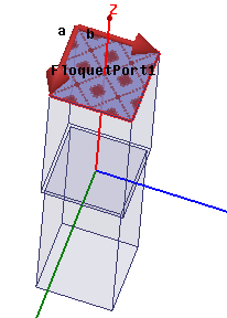
For further discussion and a sample exercise, click Help> HFSS Getting Started Guides> Floquet Ports.