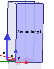
Assign Primary and Secondary Boundaries
In this section we will illustrate a key requirement for setting up a unit cell--the perimeter of a Floquet port must be covered by Primary and Secondary boundaries. You will assign the boundaries as follows:
- Select the face of the box and click HFSS> Boundaries>
Assign> Coupled> Primary.
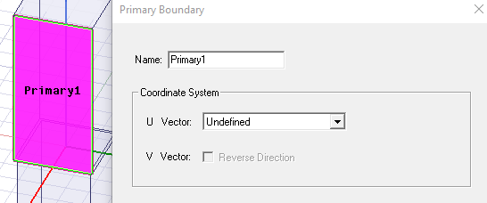
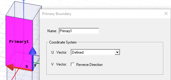
- Select New Vector from the the U Vector menu and draw the
U-V vectors as shown below, from right edge to left.
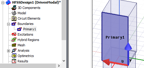
The Primary1 boundary gets assigned as shown in the following figure.
- Access the face opposite to Primary1 and click HFSS>
Boundaries> Assign> Coupled> Secondary.
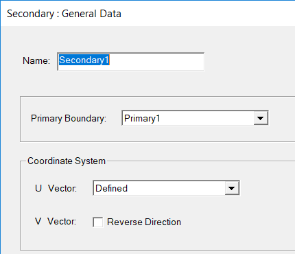
- Assign the secondary boundary as shown in the following figure.