Create and Use Custom Array By File in SBR+ Simulation
This chapter provides a summary and a detailed workflow for using Custom Antenna Arrays by File for SBR+ simulation.
Summary Workflow for Custom Array By File Antenna Arrays
- Create an HFSS design and select the SBR+ Solution Type.
- Add model objects, components.
- Add an antenna local coordinate system .
- Add the parametric antenna array by right-click on 3D Components in the Project tree and select Create Array>Custom Array By File… or right click on Excitations in the Project tree and select Create Array Component>Custom Array by File....
- On the General tab select the desired array element type from the drop down list.
- In the Create Parametric Array dialog configure any antenna-specific parameters on the “Element” tab
- On the Custom File tab, configure the array
Specify the filename of the *.sarr file to be used. These files provide array element positions, orientations, and complex weighting over a set of specified frequencies and "state". A single state must be selected for the simulation.
Select the “Active State Index” to be used for the simulation
Different weights for frequencies specified in the file can be displayed/previewed in the table shown on this tab.
- Click Preview to see a preview visualization of the array in the 3D modeler window
-
Click OK to dismiss the dialog and create the 3D component instance
- Add an Analysis Setup
- Run simulation
- Generate far field radiation pattern
Detailed Workflow for using Custom Array by File... in SBR+ Simulation
- Create an HFSS design and select the SBR+ Solution Type.
- Add model objects, components.
-
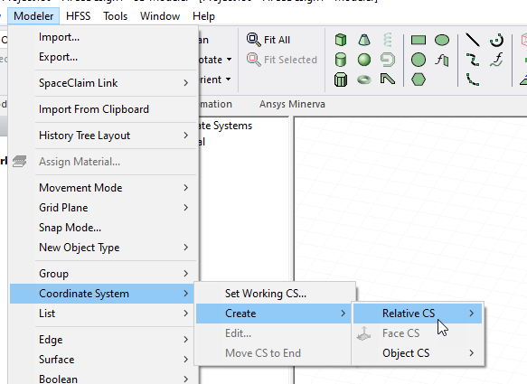
Add an antenna local coordinate system. Creation of an antenna local coordinate system (CS) can be very useful in placing and orienting parametric antennas and arrays via 3D components. The CS can be created as a simple relative CS, or as something more advanced and suitable for array placement on a surface, like a face CS . After creating the new CS, make sure it is selected/active when creating the parametric array.
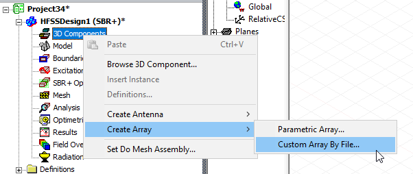
- Add the parametric antenna array by right-click on 3D Components in the Project tree and select Create Arrayy>Custom Array By File… or right click on Excitations in the Project tree and select Create Antenna Component>Custom Array by File....
This opens the Create Array dialog box with Custom File selected as the Setup Type. For creating parametric arrays, Wizard mode is not used.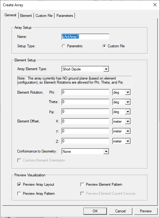
- In the Create Array dialog
- Select the Array Element Type of antenna from the drop-down menu. You can select any of the fifteen parametric antenna types as the Array Element.
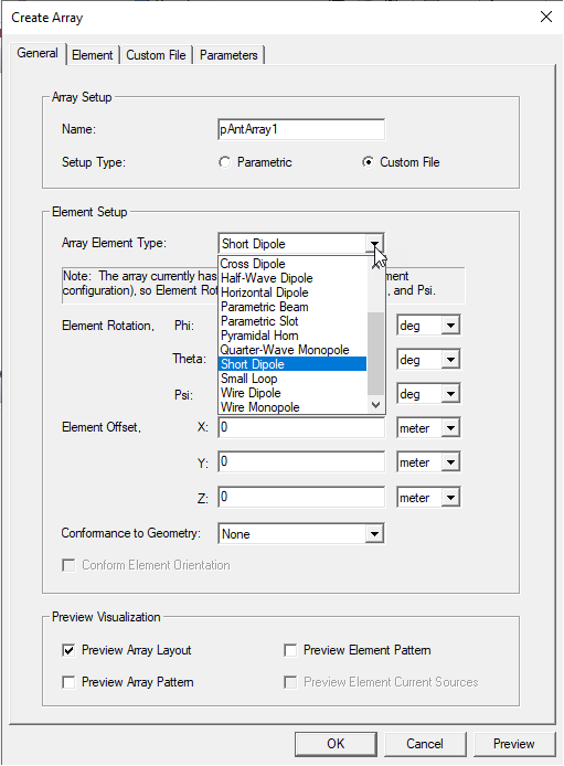
Specify the Element Rotation for Theta, Phi and Psi (all 3 quaternion rotations) and select the units from the menus. Click Preview for a display in the Model window.
- You can also specify an Element Offset for X, Y, and Z, and specify Units. After you have specified a value, and the cursor to another text box, the Preview button is enabled, allowing you to view the visualization for the values you have specified.
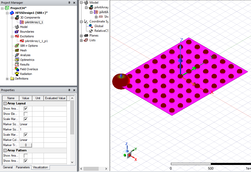
- Use the checkboxes to Preview Array Layout, Array Pattern, Element Pattern, and Current Sources (when an element type with current sources is selected). The next figure shows both Array Layout and Array Pattern after clicking Preview.
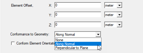
- You can use the Conformance to Geometry dropdown to select None, Along Normal, or Perpendicular to Plane. Making the selection Along Normal enables the Conform Element Orientation checkbox.
The following figure shows Conformance Along Normal relative to a sphere.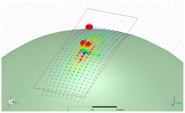
For a technical discussion, see Technical Notes: Current Conformance in SBR+. - Configure the array element. The parameters available on the Element tab (or the Element wizard page) will vary depending on the Antenna Element Type chosen. For example, the Short Dipole antenna only shows the Array Element Type as Short Dipole with no additional parameters, since this simple antenna element type has no parameters to configure. Most of the antenna element types will have some additional parameters to configure on this tab/page.
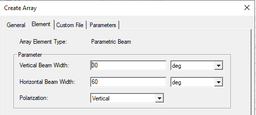
If you specify variables for any of the parameters, these will be displayed in the Parameters tab.
- Select the Array Element Type of antenna from the drop-down menu. You can select any of the fifteen parametric antenna types as the Array Element.
- If you want to edit the antenna placement, or orientation, select the model in the History tree, and right-click and select Edit>Arrange, and select from Move, Rotate, or Mirror. When you select the Parametric Array, the icons in the ribbon are also enabled.
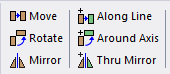
If needed, place and orient (Move, Rotate, Mirror) the 3D component at the desired geometry location.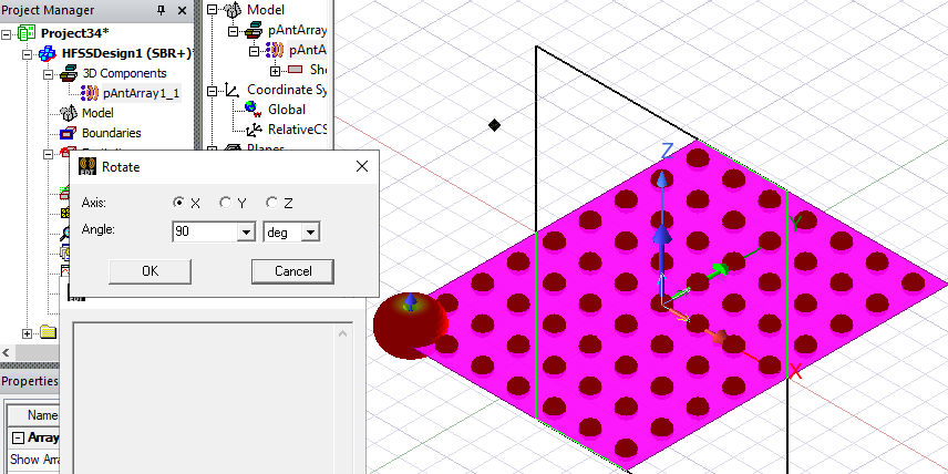
Notice that other edit commands for Copy, Paste, and Duplicate are also available. You can also change or edit the target coordinate system in the instance Property window.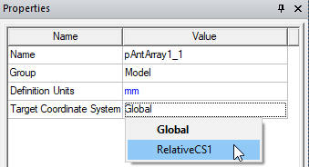
- On the Custom File tab, select the Array file to configure the array.
- Specify the filename of the *.sarr file to be used. These files provide array element positions, orientations, and complex weighting over a set of specified frequencies and "state". A single state must be selected for the simulation.
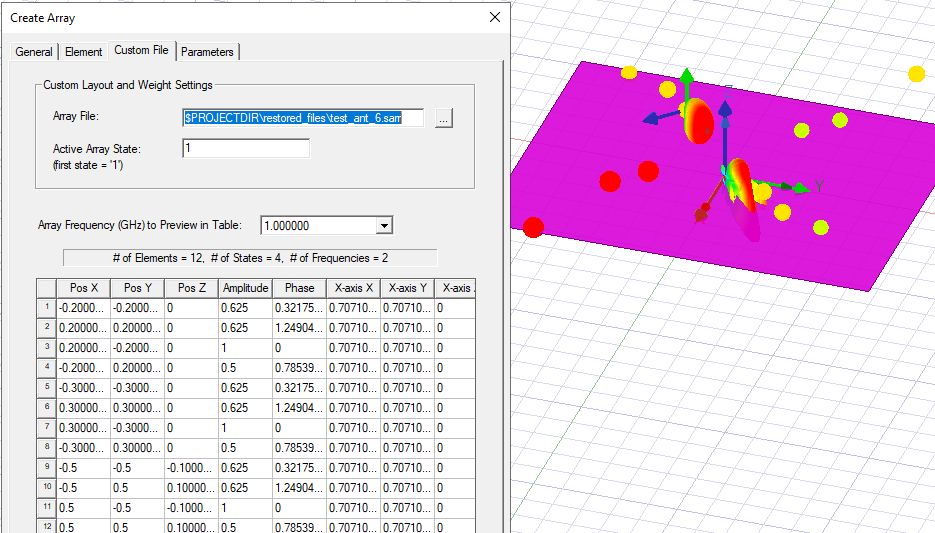
Select the “Active State Index” to be used for the simulation
Different weights for frequencies specified in the file can be displayed/previewed in the table shown on this tab
- Close the dialog with OK to save this component definition and create the parametric array 3D component instance
- Specify the filename of the *.sarr file to be used. These files provide array element positions, orientations, and complex weighting over a set of specified frequencies and "state". A single state must be selected for the simulation.
- You can view and edit the 3D component definition in the History tree. Selecting the 3D Component and Edit Properties opens the Create Parametric Array dialog and lets you edit the Properties as you did in creating the Parametric array.
- You can view and edit the properties of the 3D Component instance listed in the Project tree. Select an array antenna instance listed under 3D Components, or in the Model tree listed under one of the created Model component definitions. For each component instance that is created, there are unique instance-level properties separate from the array geometry/weighting definition that can be configured for visualization, etc. They are grouped into 3 separate tabs for General, Parameters, and Visualization.
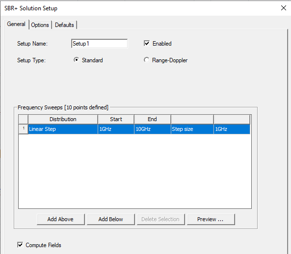
- Add an SBR+ Solution Setup. To generate a far field radiation pattern for this parametric array, be sure Compute Fields is checked on the General tab.
Also ensure that a far field Observation Domain has been correctly configured.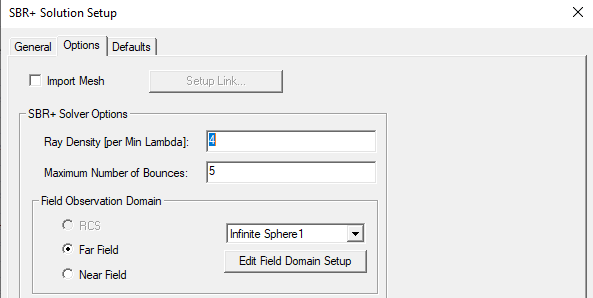
You must create a Far Field Setup to access the Far Fields and Antenna Parameters reports.
-
You may select Use Per-Element Power Specification for a Parametric Array in the Edit Sources dialog when only a Parametric Array exists in the scene. When you select that option, Edit Sources defines the input power of an element before applying the Aperture Taper configured in Array Weightings. The Parametric Array with this option gives results similar to HFSS post-processing feature of Antenna Array. Coupling analysis and Enhanced Radiated Power Accuracy are not supported.

- Run simulation.
- Generate far field radiation pattern. Right-click on the Result node in the Project Manager and select Create Far Fields Report > Radiation Pattern to create a radiation pattern plot for the desired range of theta/phi angles
After you run an SBR+ simulation with parametric antennas, the results available are just like for a single-port parametric antenna. You can create a variety of reports, including S Parameters, Far Fields, and Antenna Parameters.