Assign Gradient Surface Roughness Boundaries
Gradient Surface Roughness Boundaries address the situation where the conductors drawn in the model are perfectly smooth, but the manufactured surface is bumpy at microscopic scale. It generates a frequency dependent dataset for resistance and reactance values behind the scene for solve.
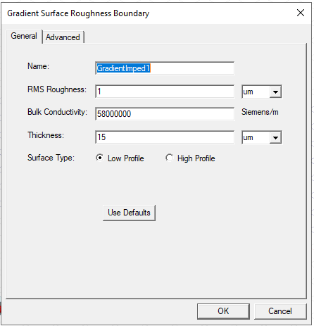
Parameters of the gradient model in HFSS are:
- The RMS Roughness parameter describes the root mean square (RMS) roughness of the surface (Rq). It is routinely measured by manufacturers, and can be entered as a value with units.
- The metal’s bulk conductivity.
- The conductor thickness.
- The surface profile. Choose Low-Profile for low-profile foils and polished surfaces, and High-Profile for high-profile foils and rough conductors.
- On the Advanced tab, the maximum frequency of interest in the simulation.
The next section first describes how to assign a Gradient Suface Roughness Boundary and the subsequent section provides a technical overview.
Assigning Gradient Surface Roughness Boundary
- Select a surface on which to assign the boundary, right-click Assign Boundary > Gradient Surface Roughness or Assign Boundary> Surface Roughness>Gradient... to bring up the Gradient Surface Roughness Boundary dialog box.
- Set the Parameters. and click OK. The boundary is listed in the Project Manager and displayed in the Modeler window.