


VM-WB-MECH-029
VM-WB-MECH-029
Elasto-Plastic Analysis of a Rectangular Beam
Overview
| Reference: | Timoshenko, S. (1956). Strength of Material, Part II: Elementary Theory and Problems (3rd Edition). New York, NY: D. Van Nostrand Co. (Article 64) 349. |
| Solver(s): | Ansys Mechanical |
| Analysis Type(s): | Static Plastic Analysis |
| Element Type(s): | Solid |
Test Case
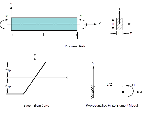
A rectangular beam is loaded in pure bending. For an elastic-perfectly-plastic stress-strain behavior, show that the beam remains elastic at M = Myp = σypbh2 / 6 and becomes completely plastic at M = Mult = 1.5 Myp.
| Bilinear Kinematic Hardening Material Properties | Geometric Properties | Loading |
|
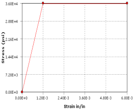
Young's Modulus E = 30 x 106 psi Yield Strength σyp = 36000 psi Tangent Modulus = 0 psi Poisson's Ratio ν = 0.0 |
Length L = 10 in Width B = 1 in Height H = 2 in |
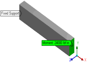
M = 1.0 Myp to 1.5 Myp (Myp = 24000 lbf - in) Applied in four steps |
Mesh Controls and Symmetry
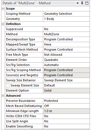
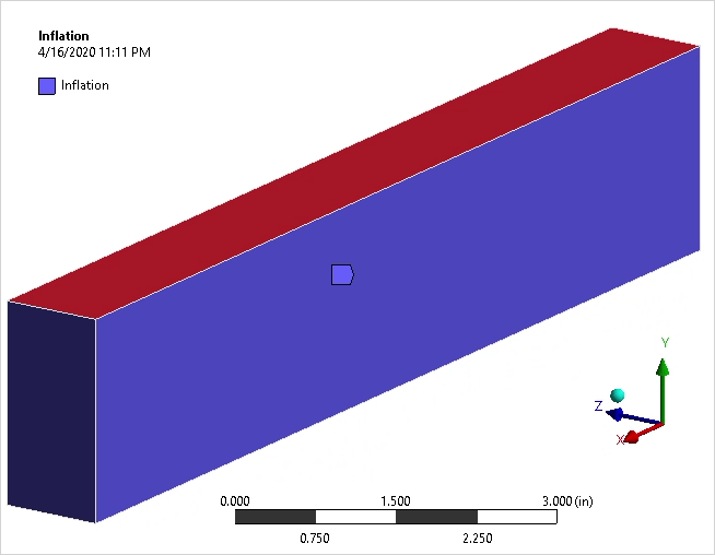
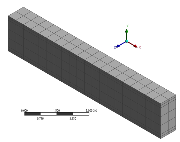
For each mesh control, the settings shown in Figure 35 and Figure 36 are used. Inflation mesh control is added to the body using the top and bottom faces as the boundaries.
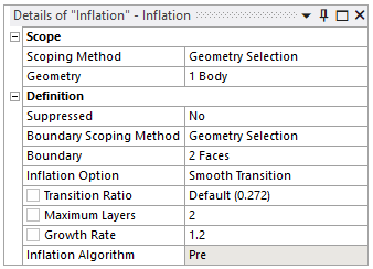
For the MultiZone Mesh Method, Hexa is used for the Mapped Mesh Type. For Element Order, Quadratic (Higher Order) is used.
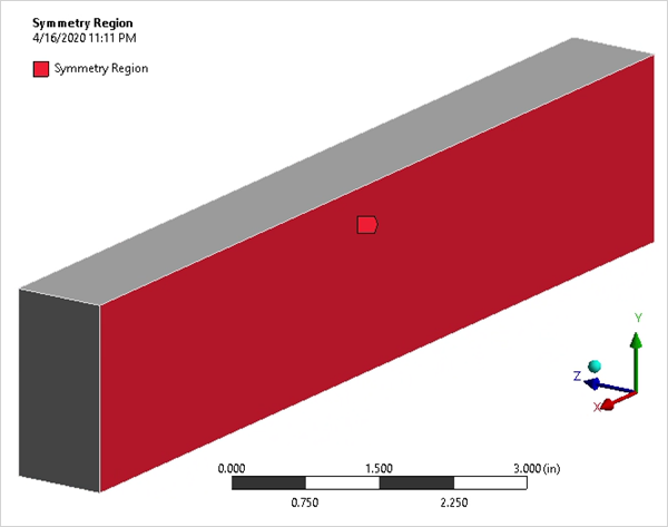
A symmetric boundary condition is applied in the global Z direction on the vertical face of the beam.
Analysis
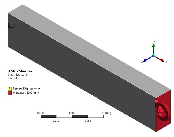
Manual Mesh Control is set to Geometry, and Full Brick Integration Scheme is selected for the analysis. Two Remote Points are created, one on each end face with Rigid behavior for applying the load and for setting the boundary conditions. One end of the beam is fixed by applying Remote Displacement scoped to Remote Point. Moment load is applied on the other end using Remote Point in four steps: M1 = 24000 lbf-in, M2 = 28000 lbf-in, M3 = 32000 lbf-in and M4 = 36000 lbf-in. Analysis settings for Force and Displacement Convergence are set to On.
Results Comparison
Moment load is applied in four steps, and Directional Deformation in the Y direction on the center node of the free face (on which Moment load is applied) is compared.
Because solid elements do not calculate node rotation at the free end, directional deformation is used as the target for validating results.
This model is not robust at M/Myp = 1.5, often resulting in an unconverged solution. Invalid results can also occur due to a plastic strain discontinuity at the neutral plane of the beam.
| M/Myp | Target | Mechanical |
Error (%) | ||
| State | Directional Deformation (in) | State | Directional Deformation (in) | ||
| 1 | fully elastic | 0.06 | fully elastic | 0.060001 | 0.002 |
| 1.1666 | elastic-plastic | 0.072964 | elastic-plastic | 0.07284 | -0.17 |
| 1.3333 | elastic-plastic | 0.10136 | elastic-plastic | 0.10101 | -0.345 |
| 1.5 | plastic | solution not converged | plastic | solution not converged | - |