


The role of a Connection Group folder is to provide you with the ability to automatically generate contact or joint objects for the whole model, or for a group of bodies within the model, with a tolerance value applied only to this group. Only these two types of connections are provided with the automatic detection capability and only one type of connection object can be included in a Connection Group folder with the exception of Spot Weld (see details in the Spot Weld section). The generated objects are placed in a Connection Group folder that is automatically renamed to "Contacts" or "Joints" depending on the type.
When you import your model into Mechanical, by default, contact detection is performed automatically. This is based on the setting in the Workbench Options dialog. On the Workbench Project Page, under > > Mechanical, there is a setting labeled Auto Detect Contact On Attach. This setting is selected by default. Furthermore, this automatic contact detection is based on the settings you define in the Options dialog (Connections category > Auto Detection) of the Mechanical application. To open the Options dialog in Mechanical, select the icon available beside the Help drop-down menu on the title bar. The File tab contains this option as well.
Detailed steps for auto/manual generating connection objects are presented in the Connection Features and Operations section.
The Connection Group has the following properties.
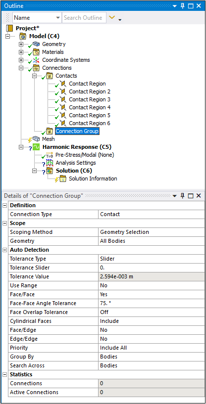
Definition
Connection Type: Options include and .
Scope
Scoping Method: Options include (default) and .
: Select geometric entities. Display when Scoping Method is set to Geometry Selection.
: Select from the drop-down list of available Named Selections. Appears when Scoping Method is set to Named Selection.
Tolerance Type: Options include , , and . Bodies in an assembly that were created in a CAD system may not have been placed precisely, resulting in small overlaps or gaps along the connections between bodies. You can account for any imprecision by specifying connection detection tolerance. This tolerance can be specified by value when the type is set to and , or sheet thickness of surface bodies when the type is set to . This option is only applicable to Contact and available when the Group By property (see below) is set to None or Bodies.
Tolerance Slider: Displays when the Tolerance Type is set to . To tighten the connection detection, move the slider bar closer to +100 and to loosen the connection detection, move the slider bar closer to -100. A tighter tolerance means that the bodies have to be within a smaller region (of either gap or overlap) to be considered in connection; a looser tolerance will have the opposite effect. Be aware that as you adjust the tolerance, the number of connection pairs could increase or decrease.
Tolerance Value: Displays when the Tolerance Type is set to or . This field is read-only if the Tolerance Type is set to , showing the actual tolerance value based on the slider setting. When the Tolerance Type is set to , you can provide an exact distance for the detection tolerance.
After you provide a greater than zero value for the Tolerance Value, a circle appears around the current cursor location as shown below.
The radius of the circle is a graphical indication of the current Tolerance Value. The circle moves with the cursor, and its radius will change when you change the Tolerance Value or the Tolerance Slider. The circle appropriately adjusts when the model is zoomed in or out.
Use Range: Displays when the Tolerance Type property is set to or . Options include and (default). If set to , you will have the connection detection searches within a range from Tolerance Value to Min Distance Value inclusive.
Min Distance Percentage: Displays when Use Range is set to . This is the percentage of the Tolerance Value to determine the Min Distance Value. The default is 10 percent. You can move the slider to adjust the percentage between 1 and 100.
Min Distance Value: Displays when Use Range is set to . This is a read-only field that displays the value derived from: Min Distance Value = Min Distance Percentage * Tolerance Value/100.
Thickness Scale Factor: appears if Tolerance Type is set to . The default value is .
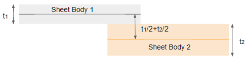
Use Sheet Thickness will use sheet bodies' thickness values (t1 and t2 above) to find contact between bodies. For example, if the sheets are within t1/2 + t2/2 * Thickness Scale Factor, then Sheet Body 1 and Sheet Body 2 would be found to be in contact.
Note: If sheet bodies and/or shell thicknesses are not precise, the default value could result in some missing contact areas. Increasing the Thickness Scale Factor to a larger value, say 1.1, may help in such cases.
For Edge/Edge pairing (see below), the largest thickness among the surface bodies involved is used; however, if the pairing is Face/Edge, the thickness of the surface body with the face geometry is used.
Face/Face (Contacts only): Options include (default) and . Detects connection between the faces of different bodies. The maximum allowable difference in the normals for which contact is detected is 15 degrees. For Joints, Face/Face is the only detection type allowed. That is why the property does not appear in the Details view when the Connection Type is Joint.
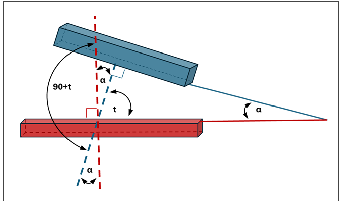
Face/Face Angle Tolerance: Visible when Face/Face = , this property acts as a geometric filter during automatic contact detection to determine how “parallel” two faces must be before they can form a contact pair. This filter considers the relative orientation of the two surface normals.
The tolerance value, t, defines the allowable deviation from parallelism. The angle between the two surface normals is 90° + t, which corresponds to a face‑to‑face angle of: α = 90° - t.
A contact pair is generated only if the actual angle between the two faces, α, is less than or equal to this allowable value.
Large t ⇒ Small allowable α ⇒ Stricter (faces must be more perfectly parallel)
Small t ⇒ Large allowable α ⇒ More permissive (more pairs considered)
By default, t = 75°, giving α = 15°, meaning only faces within 15° of parallel are eligible for proximity-based contact detection. Faces that diverge more than this angle are ignored by the automatic algorithm.
The table below shows application behavior within the acceptable tolerance range of t from 0° to 90°.
Tolerance (t) Allowable α Result 0° 90° No Filtering: All face orientations qualify for consideration. 75° (default) 15° Standard: Only mostly parallel faces are considered. 90° 0° Strict: Only perfectly parallel faces are considered. This setting is especially important in complex assemblies because it prevents the Mechanical application from generating unwanted or unrealistic face‑to‑face contact pairs between surfaces that are close in space but not meaningfully oriented toward one another.
Face Overlap Tolerance (Contacts only): This property is only visible when the Face/Face property is set to Yes. It sets the tolerance for overlap of faces in contact; that is, the minimum percentage of overlap at which a contact pair is created for two overlapping faces. For example, if Face Overlap Tolerance is set to 25, a contact pair is created for each pair of faces for which at least 25% of one face overlaps the other. You can set a value from 0 to 100 or retain the default. Setting the tolerance to 0 turns off the overlap checks.
Note: If the Face/Face property is set to and you change the Group By property setting to , the Face Overlap Tolerance property is automatically set to
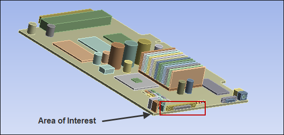
5%. This means that the application only detects contact pairs with at least 5% overlap between their respective faces. This setting remains in effect even if you change the Group By property back to another option.The following images illustrate the use of Face Overlap Tolerance. For the image of the circuit board below, Discovery's Imprint tool was used to get common boundaries between parts, and then the model was loaded into Mechanical. Notice the area of interest.
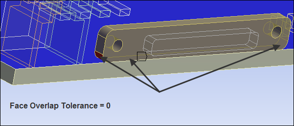
In general, the smaller the face overlap tolerance, the greater the chance that contact will result in extra pairs. The image below shows an enlarged view of the area of interest when a single Contact Region was selected in the tree. With Face Overlap Tolerance set to 0, the 3 faces identified by the arrows were scoped automatically to the Contact property of the Contact Region, and 1 face (the large blue face) was scoped automatically to the Target property of the Contact Region.
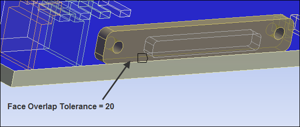
To get more precise contact pairs, you can increase the value of Face Overlap Tolerance. In the image below, the same Contact Region was selected in the tree but Face Overlap Tolerance was set to 20. In this case, the 2 small fillets were not found to be in contact with the large blue face, so only the 1 face identified by the arrow was scoped to the Contact property of the Contact Region, and 1 face (the large blue face) was scoped to the Target property of the Contact Region.
Cylindrical Faces (3D Only): This property is only visible when the Connection Type property is set to and the Face/Face property is set to . Available options are (default), , and . This property determines how the application handles cylindrical faces during automatic contact generation either upon geometry attach or manually on a Connection Group. For example, given a simulation that contains bolted joints, where the bolt shank should have frictionless contact applied and the bolt head should have bonded contact applied. Setting this property appropriately creates contacts during automatic generation that define cylindrical contact ( setting for the bolt shank) and the flat contact ( for the bolt head).
Face/Edge: Options include , (default), , , and . Detects connection between faces and edges of different bodies. Faces are designated as targets and edges are designated as contacts. To determine connection with all faces, for , face to edge connection uses the edges of solid bodies; for , it uses only edges of surface bodies; and for , it uses only edges of beam bodies.
Edge Overlap Tolerance (Contacts only): This property is visible only when the Face/Edge property is set to Yes, Only Solid Body Edges, or Only Surface Body Edges. It sets the tolerance for overlap of an edge and a face in contact; that is, the minimum percentage of overlap at which a contact pair is created for an edge and a face that overlap. For example, if Edge Overlap Tolerance is set to 25, a contact pair is created for an edge and a face when at least 25% of the edge overlaps the face. You can set a value from 0 to 100 or retain the default. Setting the tolerance to 0 turns off the overlap checks.
Edge/Edge: Options include and . Detects connection between edges of different bodies.
Priority: Options include , and . For very large models the number of connection objects can sometimes become overwhelming and redundant, especially when multiple detection types are chosen. Selecting some type of priority other than Include All will lessen the number of connection objects generated during Create Automatic Connections by giving designated connection types precedence over other types. gives Face/Face option precedence over both Face/Edge and Edge/Edge options. It also gives Face/Edge option precedence over Edge/Edge option. In general, when Face Overrides priority is set with Face/Edge and Edge/Edge options, no Edge/Edge connection pairs will be detected. Edge Overrides gives Edge/Edge option precedence over both Face/Edge and Face/Face options, no Face/Face connections pairs will be detected.
Group By: Options include , (default), , and . This property enables you to group the automatically generated connections objects. Setting Group By to (default) or to means that connection faces and edges that lie on the same bodies or same parts will be included into a single connection object.
Note: When the Connection Type property is set to and this property is set to :
The application automatically creates contact between faces or edges across multiple bodies or parts and groups them by faces.
Contact Regions that have either the same scoping on the target side and/or overlapping scoping on the contact side are merged.
The option is only supported when the Face/Face property is set to or the Face/Edge property is set to any option other than
When the Face/Face property is set to and you change the setting of this property to , the Face Overlap Tolerance property is automatically set to
5%. This means that the application only detects contact pairs with at least 5% overlap between their respective faces. It is important to note that this tolerance value is fixed and does not change when the Group By property is modified to any other setting.When you create automatic contacts by defining multiple Connection Groups for different bodies, the option does not merge contacts with overlapping or identical scoping across different Connection Groups. Use the Check Overlapping Contact Regions context menu option to find overlapping regions within the same Connection Group. If overlaps occur between different Connection Groups, you need to manually identify and merge those contacts.
- Recommendation
When the Connection Type property is set to , Ansys recommends using the option to:
Reduce over-constraint issues associated with MPC formulation-based contacts, especially when multiple contact regions share the same target faces or have overlapping scoping.
Minimize the number of contact regions created, which typically decreases overall computational time. For example, if you have a PCB model where multiple contact regions share a common target face, merging contacts significantly reduces solution processing time.
When you set the property to , the application does not group geometries that lie on the same bodies or same parts. Therefore, any connection objects generated will have only one entity scoped to each side (that is, one face or one edge). This setting is useful if:
There are a large number of source/target faces in a single region. This avoids excessive contact search times by the Mechanical APDL solver.
You want to define different contact behaviors on separate regions with contact of two parts. For example, for a bolt/bracket contact case, you may want to have bonded contact between the bolt threads/bracket and frictionless contact between the bolt head/bracket.
Search Across: This property enables automatic connection detection through the following options:
Bodies (default): Between bodies.
Parts: Between bodies of different parts, that is, not between bodies within the same multibody part.
Assemblies: Between bodies from different sub-assemblies (sources) in an Assembled Model.
Anywhere: Detects any connections regardless of where the geometry lies, including different parts. However, if the connections are within the same body, this option finds only Face/Face connections, even if the Face/Edge setting is turned On.
: Between bodies from different External Model source files and between copies of an External Model source file.
Fixed Joints: (Joint only) options include and . This property determines if Fixed Joints are to be automatically generated. See the Automatic Joint Creation section for details.
Revolute Joints: (Joint only) options include and . This property determines if Revolute Joints are to be automatically generated. See the Automatic Joint Creation section for details.